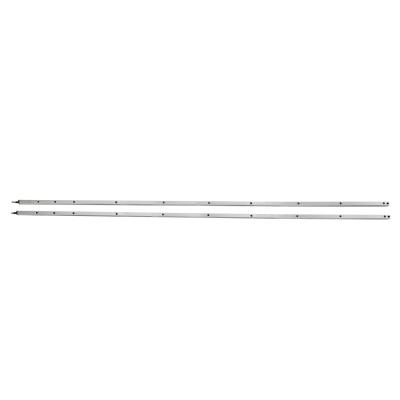
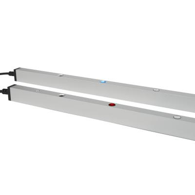
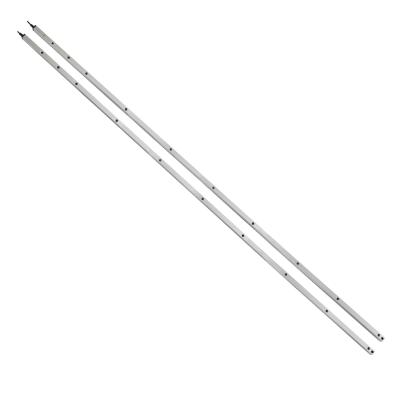
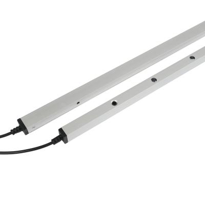
CL10-8L Infrared Safety Light Curtain Sensor with Blanking Function for industry Door
Product Description

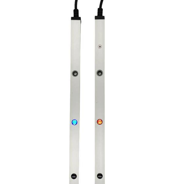
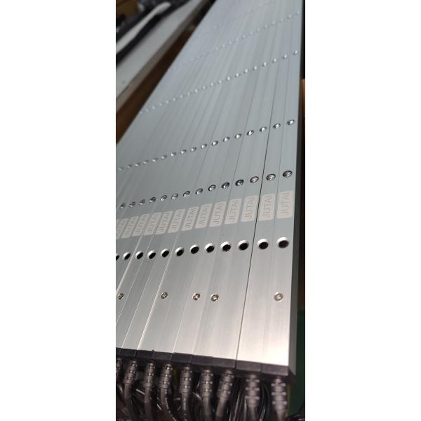
JUTAI IP67 CL10-8L Safety Light Curtain
Blanking Mode:
- Installed inside the door gap. When the door closes normally, the light beams of the safety light curtain are sequentially blocked from top to bottom. This sequential blocking is recognized by the system as a normal door closing action. However, if an object passes below and blocks the light beam when the door is in the process of closing, it will trigger the door to open.
Normal Mode:
- Installed on the inside and outside of the door. When the door is closed, the light beams are not passed through. In this mode, regardless of which light beam is blocked, the system will immediately output the door opening signal.
Advantages:
- Suitable for cold storage doors and humid environments down to -25℃.
- No need for a synchronous wire control box.
- Ultra-fast response speed of just 0.03 seconds.
- Resistant to sunlight and electromagnetic interference.
- Supports customization (in terms of quantity).
Technical Specifications
Model | CL10-8L |
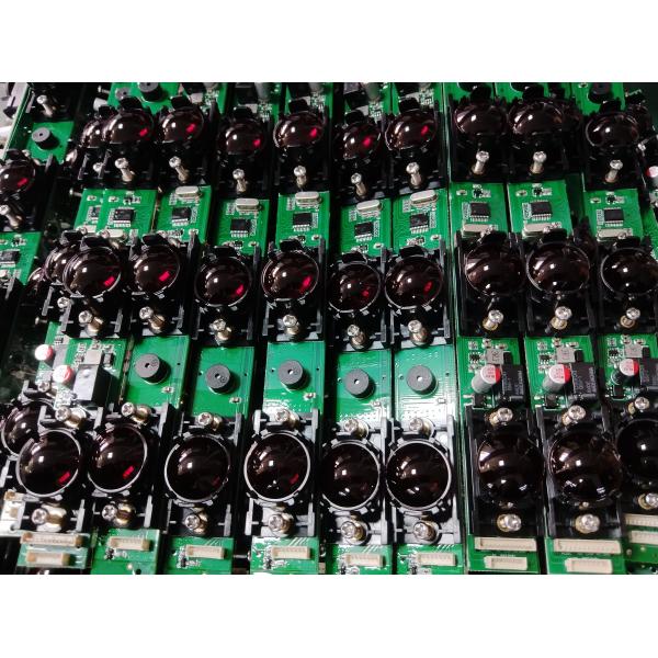
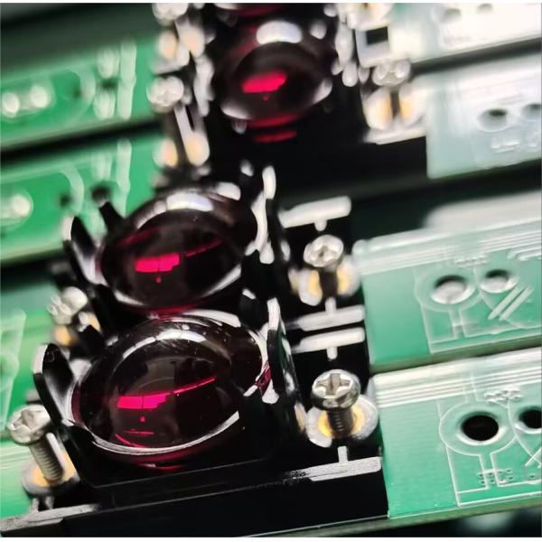
Technology | Active Infrared Sensor with Strong Light Resistance |
Detection Range | Up to 8 meters |
Response Time | Fast and reliable |
Working Current | <20mA at DC12V |
Working Voltage | DC12-24V |
Output Methods | NO/NC and COM |
Applications | High-speed doors, sectional doors, rolling doors, vertical closing telescopic doors, freight elevators |
Protective Height | Max 800mm |
Operating Temperature | -25 ~ +70℃ |
Protection Level | IP67 |
Shell Material | Aluminum alloy |
Installation Guidelines for JUTAI IP67 CL10-8L Safety Light Curtain
Step 1: Prepare for Installation
- Detach Covers: Gently remove the top and bottom covers of the sensor.
- Wire Connections: Make the necessary wire connections and thread the end through the designated port.
Step 2: Determine Installation Position
- Alignment: Align the transmitter and receiver in parallel to find the exact installation spot.
- Marking: Precisely mark the hole positions on the wall for accurate drilling.
Step 3: Drill and Secure
- Drilling: Use a percussion drill to create holes at the marked locations.
- Securing: Insert wall plugs into the drilled holes and fasten them with screws.
Step 4: Mount Components and Adjust
- Mounting: Attach the transmitter and receiver to the wall using M3*25 screws.
- Power Connection: Connect the power supply and test the alignment of the sensor.
- Adjustment: If required, adjust the angle by rotating the aluminum tube. Once aligned properly, tighten the rotating screw firmly.
Step 5: Finalize Installation and Test
- Reattach Covers: Reattach the top and bottom covers using M2*8 screws.
- Final Test: Conduct a thorough test to ensure the sensor functions correctly.