Dynamic Voltage Regulator (DVR)
When the power line undergoes a voltage sag or surge, this may cause a critical security threat in power supplying for an enterprise. More seriously, it may cause significant property loss and personal loss. Use of a DVR alleviates such a threat or even avoids related loss.
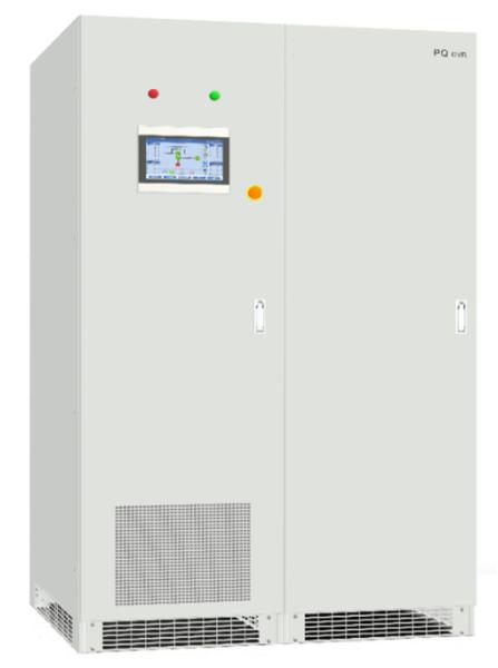
A DVR is a cutting-edge power electronic device. It employs both advanced power electronic semiconductor technologies and control technologies to ensure safe use of electricity. To ensure stable power supplying to sensitive devices at the backend, our DVR uses world-leading control chips such as DSP/FPGA/CPLD to monitor line voltage quality. When a voltage sag or surge is detected, our DVR can instantly switch related backend devices to be powered by an inverter. The manipulation and shutdown of our DVR is controlled by software, and its typical switching cycle may be limited to no more than 1ms, making sure that the power supplied to the devices will not be interrupted. You can select supercapacitors or lithium batteries as backup power sources to meet your own requirements. The duration for backup power supplying depends on the capacity of those supercapacitors or batteries.
Product Features
DVR Working Principle
Our DVR is connected in parallel within a power grid system. When the grid voltage is normal, an SCR on the power source side is connected, and the power grid can directly feed various devices. At the same time, a bi-directional inverter is in a standby state and monitors in real time how the grid voltage fluctuates. | ![]() |
At the instant when an unexpected voltage fluctuation is detected, our DVR switches backend devices to be powered by a supercapacitor or other energy storage units. This ensures proper running of those backend devices will not be affected. | ![]() |
When the grid voltage goes back to normal, and our DVR determines that the power supplied meets related standards, it switches the backend devices to be powered by the power grid, and simultaneously charges the backup energy storage units over the bi-directional inverter. | ![]() |
DVR Model
DVR Technical Parameters
Series | DVR50 -150kVA | DVR200 - 350kVA | DVR400 - 450kVA | DVR500kVA or above |
System Parameters | ||||
Rated voltage | 208V, 220V, 380V, 400V, 415V, 460V, 480V | |||
Rated capacity | 50kVA, 75kVA, 100kVA, 150kVA | 200kVA, 250kVA, 300kVA, 350kVA | 400kVA, 450kVA | 500kVA or above |
Rated frequency | 50Hz/60Hz, ±5Hz | |||
Voltage range | -40% - +20% (You can set this value) | |||
DC voltage | 180 - 750Vdc (The minimum value can be adjusted as needed.) | |||
Pieces to be integrated | 8 | |||
Global efficiency | ≥99% | |||
Wiring mode | 3-phase 3-wire; 3-phase 4-wire | |||
Connection mode | Connect lines from both the top and the bottom | |||
Air in/out | Air in from the bottom and out through the top | |||
Performance Indicators | ||||
Overall response time | <1ms | |||
Voltage precision | 1% | |||
Sag compensation capability | 100%; compensation cycle 3s; for a longer cycle, add a supercapacitor as needed. | |||
Overload capability | Overload 125%, lasts at least 10min; Overload 150%, lasts at least 1min | |||
Cooling mode | Air-cooled | |||
Noise | <68dB | |||
Fixing mode | Cabinet | |||
Dimensions (W*D*H mm) | 600*1000*2000 | Power cabinet: 600*1000*2000 Super-capacity cabinet: 600*1000*2000 | Power cabinet: 600*1000*2000 Super-capacity cabinet: 800*1000*2000 | For a capacity of 500kVA or above, you can adjust as needed. |
Environment Parameters | ||||
Altitude | ≤2000m, 2000m - 4000m (De-rating) | |||
Operating temperature | -10ºC - 40ºC | |||
Relative humidity | 5% - 95%, non-condensing |
Note: For DVR products of other specifications, contact us for further information
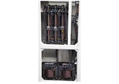
Structure of DVR50 - 150kVA