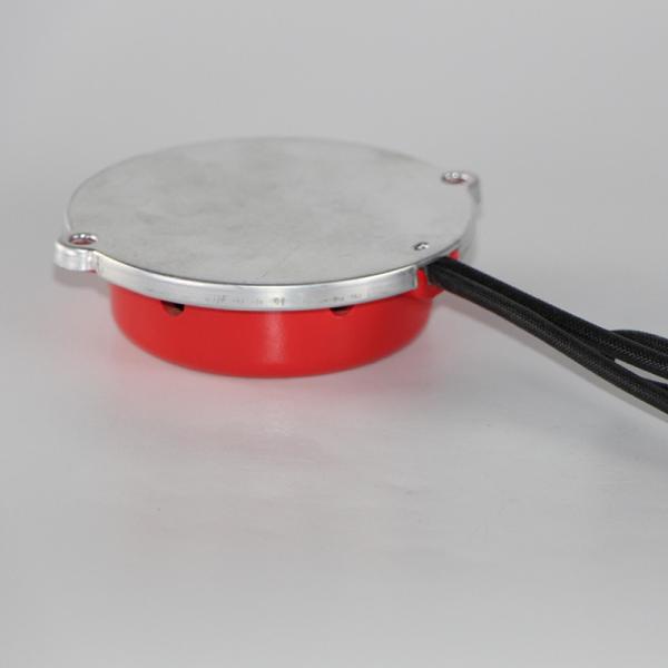
Aerosol Fire Fighting System Fire Suppression Systems for Turbine Enclosures
Inspection before using Aerosol Fire Fighting System
1.1 Please carefully read this instruction before installation and test each Aerosol Fire Fighting System and its accessories one by one according to the following inspection methods. The device can only be used after being confirmed.
1.2 Inspection method of the fire extinguishing device.
1.2.1 Appearance inspection: check the integrity of the shell and there should be no obvious paint loss, indentation and deformation. The accessories should be complete
1.2.2 Quality Inspection: There are six connecting wires in the electric starter of fire extinguishing device, of which 1 and 2 are defined as a group, 3 and 4 are defined as a group. If the resistance value is 1.0Ω~3.0Ω, the corresponding wiring is selected at the controller end to connect, and the two wires can be used in parallel. 5 and 6 are normally open / normally closed feedback ends.
Note:
Table of Product Technical Parameters
Item | Parameters |
Product model | FireLess 100 |
Dimensions (without accessories, mm) | 240 in diameter×110 in height |
Weight of fire extinguishing device (Kg) | 5.3 |
Agent quantity (Kg) | 2.8 |
Fire extinguishing performance ( g/m3) | 56 |
Start current(mA,DC) | ≥700 |
Safe current (mA,DC) | ≤150 |
Electric start time (ms) | ≤3 |
Discharge time (s) | ≤15 |
Working temperature (℃) | -50~+95 |
Service life (year) | 10 |
Thermal clearance of aerosol (m) | when400℃≤0.14 when 200℃≤0.28 when 75℃≤0.75 |
Compatibility | Can be used with fire alarm system |
Installation and Maintenance of Aerosol Fire Fighting System
2.1 Take out the fixed bracket of fire extinguishing device to fix the device. There should be no obstacle between the fire extinguishing device and the shield. Auxiliary bracket can be installed if necessary, which should be capable of bearing no less than 5 times the weight of the fire extinguishing device and ensure the firm fixation of the fire extinguishing device.
2.2 Connect the backup wire welded in section 1.2.2 of this instruction to the mechanical temperature sensing start element. If an external control system is needed, the backup wire can also be connected to the fire control manual button and fire control panel. (Note: make sure that the docking of aviation connectors is the last step.)
2.3 The device should be installed evenly in the protective space, and the distance between them should be not less than 2 meters. When the height of protective space is greater than 5 meters, it can be installed in layers, and the distance between layers should not be greater than 5 meters.
2.4 When in installation, the device must be considered to avoid high temperature area with temperature above 95°C. There should be no obstacles or flammable and explosive substances that affect the free spray of aerosol within 1 meters around the shell.
2.5 After the device has completed spray and release, its shell is at high temperature and should not be touched. Disposal of the device should be implemented after cooling through nature or other methods.
2.6 This fire extinguishing device does not require periodic quality inspections of agent within its validity. The shell of the fire extinguishing device shall regularly remove dust and dirt according to the environmental conditions, and shall be promptly replaced if any deformation or damage is found. Regularly check if there is open circuit or short circuit in wiring and whether the resistance of ignition device is normal, and record the check result.
2.7 For standard installation environment of box and cabinet, this device should be Installed and used under the guidance of fire-fighting professionals. For non-standard installation environments such as mobile and vibratory carriers, please contact the manufacturer to confirm the plan. The related losses caused by abnormal installation, maintenance and usage are not in the quality assurance scope of the company.
2.8 This device is suitable for fire hazard of Class A, B, C and E. Do not use beyond scope.