1200 tph capacity stacking and reclaiming equipment for power plant
1. Introduction
Bucket-wheel stacker reclaimer can realize the functions of continuous stacking, taking, mixing, and storage of bulk particles and block raw materials. It is widely used in the material storage and transportation system of electric power, metallurgy, building materials, chemical industry, port, coal, grain, and other industries. It is common equipment in large and medium-sized industrial enterprises.
Bucket-wheel stacker reclaimer is mainly composed of bucket wheel, slewing, boom raising, walking, cantilever belt conveyor, and metal structure, tail car, auxiliary structure, central hopper, spray dust suppression system, lubrication system, electrical system, power supply device, and so on.
By adjusting the tail car structure (fixed single tail car, semi lying tail car, full lying tail car, cross tail car, double tail car, etc.), the bucket wheel stacker reclaimer can realize many functions, such as stacking, reclaiming through, reclaiming turn back, shunting, through and so on, to meet the requirements of different working conditions.
2. Structural form of the whole machine
The medium and small bucket wheel machines adopt the overall balance form, with few movable hinge points and a low failure rate. The central hinge seat of the superstructure is equipped with lubrication-free joint bearing, with less maintenance workload. For large bucket wheel machines, the movable balance type is mostly adopted, mainly considering that the pitching angle of the cantilever frame is small and the change of the center of gravity relative to the superstructure is small.
Feature
product tracking | Stacking and Reclaiming Equipment |
painting | Jotun |
color | green |
capacity | 1200 t/character bucket |
character | Bucket Wheel |
advantage | low maintenance-benefit low |
benefit | low cost |
application | coal handling |
Complete machine type (fixed split tail car)
Complete machine type (full function tail car)
3. Main structural features and introduction
1)Crane traveling mechanism and door seat frame
(1)The portal frame adopts a three fulcrum four-leg structure to maintain the static structure of the portal frame and adapt to the height deviation of the long-distance walking track foundation.
(2)The three-in-one driving mechanism of motor, reducer, and the brake is adopted. The reducer and wheel shaft are of suit type, with compact structure and convenient disassembly and assembly. Single wheel or double wheel drive, fully sealed, suitable for high dust environment, making maintenance and repair easier and convenient.
(3)There are two kinds of running speeds, i.e. normal working running speed and nonworking shunting high-speed running speed. AC variable frequency speed regulation is adopted to avoid the impact of equipment starting and stopping.
(4)The frame of the traveling trolley adopts the balance beam device to make the wheel pressure of each wheel equal. The traveling trolley and the balance beam are split package structures, and the wheelset and traveling trolley are also split package structures, which is convenient for disassembly, assembly, and maintenance.
(5)Rail clamps and windproof anchoring devices are set in pairs under the gantry. Buffer stops, running limit switch bumpers, and limit switches are set at both ends of the track to prevent the reclaimer from derailing. The balance frame is equipped with a track cleaner to clean the track area. The clearance between the sweeper and rail surface is adjustable.
A buffer is set at the end of the balance frame to absorb the kinetic energy of the collision between the reclaimer and the bumper.
The traveling position detector shall be set and displayed in the cab.
A red flash lamp and two buzzers are set on each door leg to give audible and visual alarm when walking.
Each group of drives is equipped with a brake release switch. The traveling motor can be started only when all traveling brakes are turned on, so it is ensured that the motor can be started synchronously.
(6)Safety interlock control
When traveling at high speed, the driving device is interlocked with the boom position. Only when the boom is within the safe height and safe angle can it walk at high speed.
The drive is interlocked with the anchor.
The driving device is interlocked with a wheel clamp and rail clamp.
The driving device is interlocked with the cable coiling device.
Three fulcra four-leg portal frame
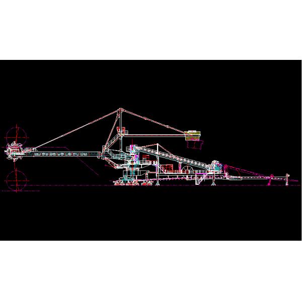
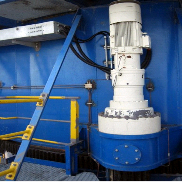
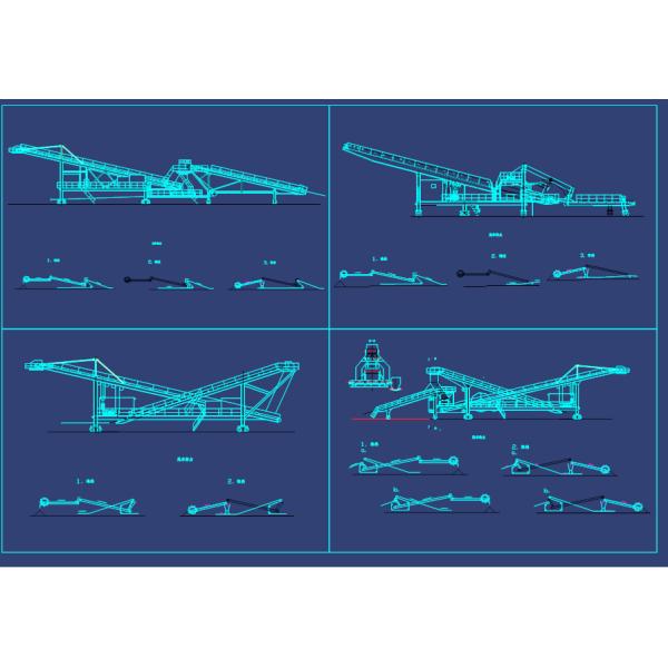
Three in one reducer with single wheel drive
Three in one reducer with two-wheel drive
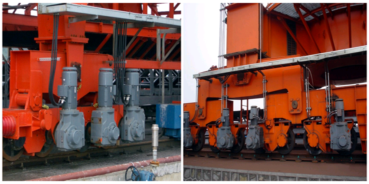
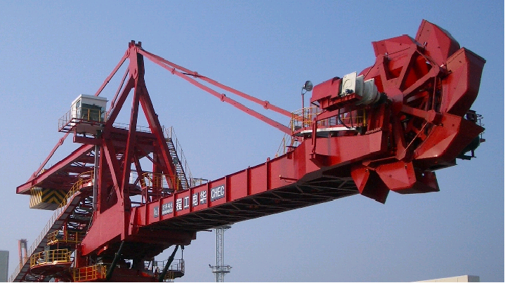
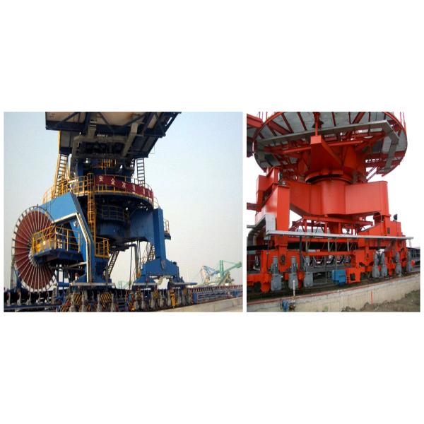
2. Bucket wheel mechanism
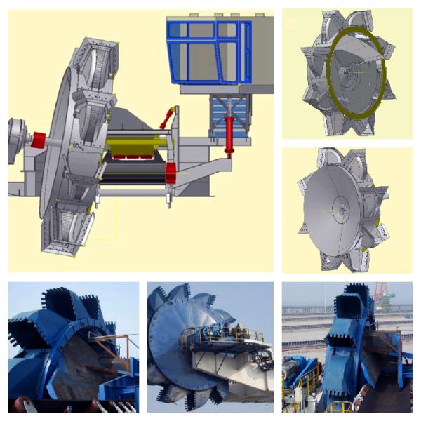
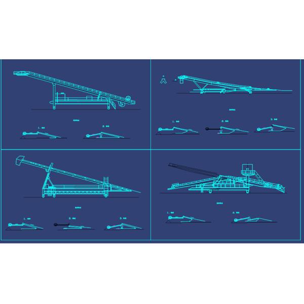
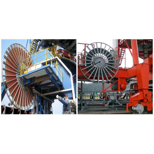
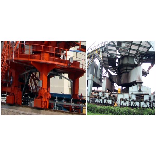
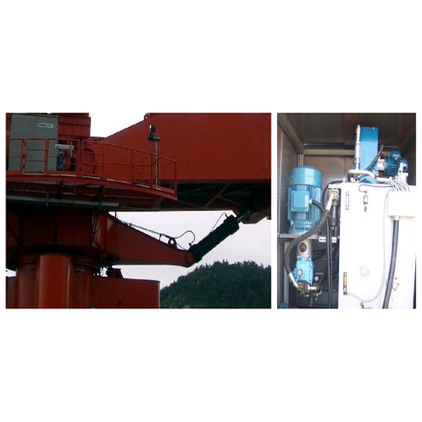
(1)The driving device of the bucket wheel mechanism is driven by an imported low-speed and high torque hydraulic motor (without mechanical deceleration device), and the supporting imported hydraulic station is adopted. The bucket wheel hydraulic system is equipped with an overpressure protection device. The connection with the output shaft is spline sleeve type, with a compact structure and convenient disassembly. To increase the unloading angle and excavation depth, the short shaft support structure is adopted, and the bucket wheel drive device is arranged on the same side as the bucket wheel.
(2)The bucket wheel body has no format. The bucket wheel body has sufficient stiffness and strength to ensure durability, good cutting angle and shape, high reclaiming efficiency, and can most effectively avoid material accumulation and wear.
(3) Wear-resistant lining plates are installed where materials such as arc baffle, chute, and guide chute are easy to be washed and worn, and the lining plates are connected with countersunk bolts for easy replacement.
(4)The bucket wheel chute baffle adopts the full lifting design, and the baffle is lifted during stacking to make the materials pass through unimpeded.
(5)The bucket wheel mechanism is equipped with safety devices such as a limited torque switch, bucket wheel speed detector, hydraulic coupling, and overcurrent protection.
3)Pitching mechanism
(1)Bucket wheel mechanism generally adopts hydraulic transmission and hydraulic cylinder pitching. The pitching motion is smooth without impact. Ensure that there is no leakage in the hydraulic system.
(2)The main components of the hydraulic system are internationally famous brand products.
(3)Double acting differential hydraulic cylinder is adopted, and a maintenance-free self-lubricating spherical sliding bearing is installed at the hinge point of the cylinder. The upper and lower oil inlet and outlet of the oil cylinder are equipped with anti-pipeline burst valves. When the pipeline breaks, the oil cylinder will be automatically locked, and the cantilever will not fall, to ensure the safety of the system.
(4)The boom is equipped with a safety rod. When repairing or replacing the oil cylinder, the boom is fixed with the safety rod to ensure safety during maintenance.
(5)Safety device
Hydraulic cylinder and hydraulic pump station of pitching mechanism
4)Rotary device
(1)The slewing adopts the support mode of three rows of roller slewing large bearings, with small resistance, good anti overturning ability, and a set of independent lubrication systems.
(2)The rotary drive device adopts motor torque limiting coupling brake vertical planetary gear reducer to drive pinion and large ring gear. The output shaft of the planetary gear reducer is equipped with a seal with reliable performance and convenient replacement, which is convenient for the disassembly and assembly of the output shaft gear.
(3) To ensure quantitative reclaiming, stable rotation start, and braking, it is driven by variable frequency speed regulating motor, controlled by VVVF, and the rotation speed is stepless regulated by 1 / cos.
(4) To ensure the meshing of large and small gears, the centerline of reducer housing and the centerline of reducer shaft is eccentrically arranged to adjust the meshing clearance.
5)Cantilever belt conveyor
(1)The driving device of the belt conveyor is composed of motor, hydraulic coupling, reducer, hydraulic push rod brake, etc. The reducer adopts the vertical shaft type reducer, which has the characteristics of a compact layout. Oil splash lubrication is adopted to ensure that the reducer is in a good lubrication state during pitching with the cantilever.
(2)Hydraulic belt tensioning device shall be adopted, and a reliable mechanical locking device shall be provided to reduce the times of belt bending and improve the service life of the belt.
(3)Safety device
The belt conveyor is equipped with safety protection devices such as belt slip detection, belt deviation detection, hopper chute blockage detection, pull-wire emergency stop switch on both sides of the belt conveyor, belt longitudinal tear detection, and so on.
(4)The cantilever belt conveyor is arranged on the inner side of the cantilever frame, and platform channels are set on both sides to facilitate the passage of maintenance personnel.
6)Upper metal structure
The upper metal structure is divided into L-shaped column type, tower column type, four connecting rod types, and other structures, which are suitable for various types of bucket wheel equipment.
7)Tail
To meet various process requirements, there are usually the following tail models:
8)Design features of each transfer hopper and wear-resistant materials:
(1)There is sufficient buffer volume at the material transfer point to prevent the accumulation of material flow in case of power loss. The guide chute is designed to be tightly sealed and equipped with an adjustable movable baffle to align the material flow on the tape. The contact part with the tape adopts multi-layer anti overflow rubber, and the rubber curtain is set at both ends of the guide chute. To prevent the overflow of material block and material powder, resulting in a lateral impact on the tape.
(2)Wear-resistant lining plate: each hopper and guide chute is equipped with wear-resistant lining plates made of 16Mn, high chromium alloy surfacing wear-resistant lining plate, and high manganese and high chromium casting wear-resistant lining plate.
9)power supply
The power supply part adopts a high-voltage power supply, generally 6kV, and sometimes 10kV. Power is supplied by a cable drum. There are two ways of cable drum:
(1)The power and control drums are separated.
(2)The power and control reels are combined into one, and the control line and optical fiber are made in the power cable to realize control and communication.
10)Spray dust suppression system
The material transfer point of the bucket wheel stacker reclaimer is designed and a complete water spray and dust suppression system is provided. The system can run continuously without fault and can be centrally controlled in the driver's room. A flushing water device is installed in the middle of the cantilever belt and on the rotary platform. When the equipment is not used, ensure that there is no ponding in the pipeline to avoid freezing of the pipeline in winter.