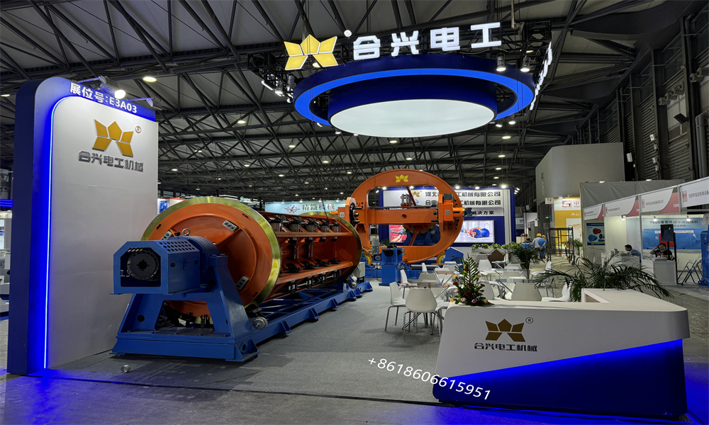
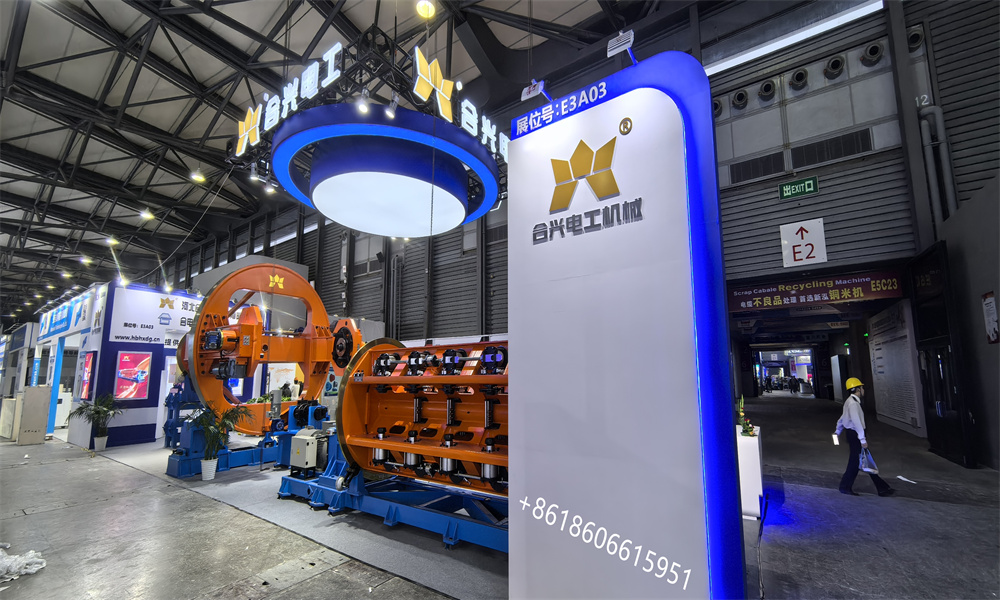
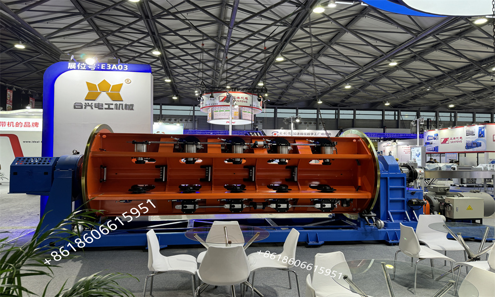
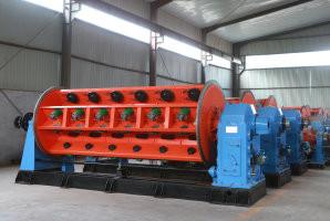
Siemens PLC Controlled Rigid Stranding Machine for Aluminum Alloy Wire Production

1. Application: This machine is mainly used to produce large section and large length ACSR,AAC wire and aluminum alloy wire; It can also be used for pressing of copper round and aluminum sector conductor.
2. Overview of equipment composition
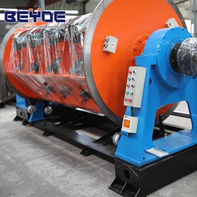
The whole machine is driven by separate motors driving. Each section of the cage and capstan is driven by a independent motor. The control of the whole machine adopts Siemens S7-200 series PLC to ensure synchronization accuracy. In actual production, the operator can set the process parameters such as the pitch of each section of the stranding cage and the speed of the production line on the touch screen according to the cable specifications to be produced, and automatically calculate the speed of each transmission part and control the pay-off tension through PLC when starting up.
Siemens S7-200 series PLC and collective PROFINET fieldbus are used for unified control of the whole machine operation to coordinate the working state, operation and speed control of all parts of the whole machine. The operation touch screen adopts Siemens color HMI to control the operation
3.Main Parameter:
| 3.1 | Input wire diameter | Aluminum Ø 1.8-Ø 5.41mm |
| 3.2 | Max stranding OD | Ø50mm |
| 3.3 | Max rotation speed | 12 bobbins | 206r/min(Full bobbins) |
| 20 bobbins | 182r/min(Full bobbins) |
| 24 bobbins | 160r/min(Full bobbins) |
| 3.4 | Strand cage motor power | 12bobbins | 55KW(AC) |
| 20 bobbins | 55KW(AC) |
| 24 bobbins | 55KW(AC) |
| 3.5 | Strand pitch(set one PLC) | 12 bobbins | 41-738mm |
| 20 bobbins | 48-860mm |
| 24 bobbins | 56-1006mm |
| 3.6 | Wire broken detection stop machine | Vector pulse type |
| 3.7 | Taping machine max rotation speed | 1500r/min |
| 3.8 | Taping machine motor power | 3.0Kw AC |
| 3.9 | Taping machine wrapping pitch | 0-100mm (Stepless adjustable) |
| 3.10 | Traction line speed | 60m/min |
| 3.11 | Max traction force | 2500kg |
| 3.12 | Caterpillar motor power | 55KW(AC) |
| 3.13 | Pay-off bobbin size in cage | PND500 |
| 3.14 | Central pay-off bobbin size | PN800-PN1600 |
| 3.15 | Take-up bobbin size | PN1000-PN2000 |
| 3.16 | Machine center high | 1000mm |
| Ø1600 Column type Pay-off stand | 1 unit |
| Well type guide wire strand | 1 unit |
| 12. 20. 24 Bobbins stranding cage | Each 1 unit |
| Side bottom automatic loading bobbins system | Each 1 unit |
| Closing wire collect stand | 3 units |
| Assembling and shaping core rod | Customer provide |
| Closing wire mould | Customer provide |
| Concentric type taping machine | 4 units |
| Mechanic digital Meter counter | 1 unit |
| 2500kg pneumatic caterpillar | 1 unit |
| Ø 2000 Portal type take-up with traverse stand | 1 unit |
| Electric control cabinet | 1 unit |
| Safety protection fence and cover | 1 unit |
- Technical parameter of each components:
- Ø1600 Column type Pay-off stand:
5.1.1. Applicable range of wire reel: PN800-PN1600
5.1.2. Applicable wire reel width: 600-1180mm
5.1.3. Maximum load capacity: 6 tons
5.1.4. Tip diameter: Ø 80/100mm
5.1.5. Tension form: mechanical friction
5.1.6 Ø 1600 end shaft type pay-off rack, with a base made of high-quality steel plates and profiles welded together, and movable columns on both sides. Two columns are fixed with two brackets of different sizes, and the large bracket end is equipped with a tension adjustment device. The column is made of high-quality steel plate bent and welded, with a beautiful appearance and good rigidity.
5.1.7. The pay-off rack can meet the requirements of Ø800- Ø1600 The clamping, loosening, lifting, and lowering actions. Ensure reliable positioning of the wire reel. The lifting mechanism can lift both left and right simultaneously, and can also be moved independently. The left column can be moved independently for easy clamping of the wire reel. Electrical limit protection is used for up and down lifting.
5.1.8. The pay-off tension is provided by mechanical friction, and the tension can be manually adjusted
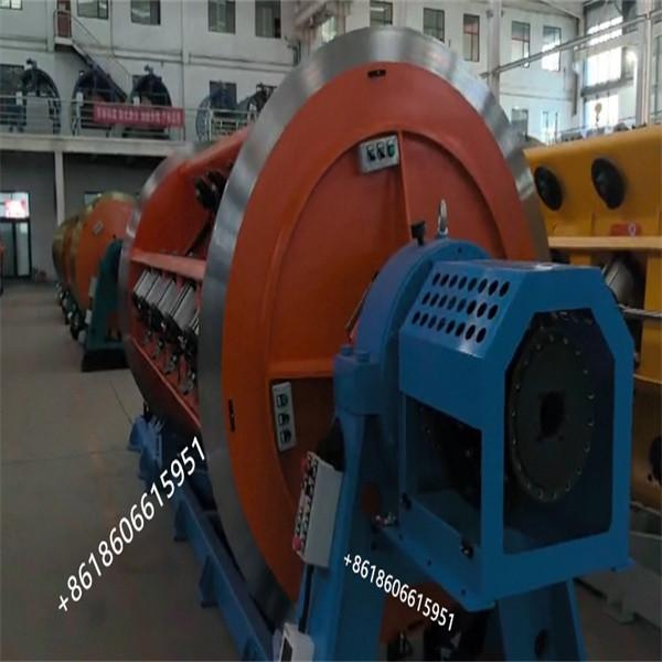
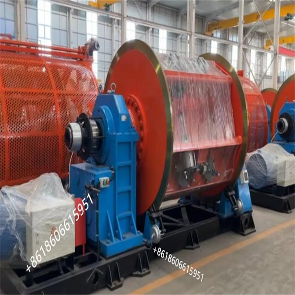
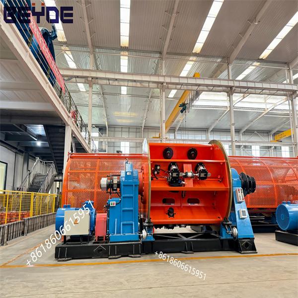
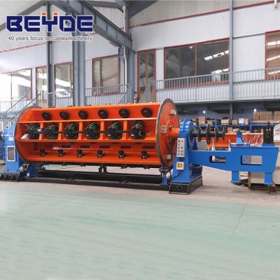
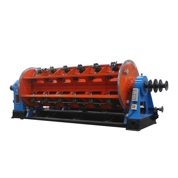
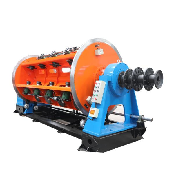
- 12+18+24 bobbin stranding cage:
5.2.1. Specification of pay-off bobbin in cage: PND500
5.2.2. Applicable bobbin diameter: Ø500mm
5.2.3. Applicable bobbin width: 375mm
5.2.4. Broken wire stop machine system: full-automatic vector pulse type
5.2.5. Loading and unloading bobbin method: centralized side bottom automatic
5.2.6. Hardness of the tightening needle of bobbin: ≥ HRC50
5.2.7. Pay-off tension: pneumatic constant tension+mechanical tension
5.2.8. Stranding cage drive form: direct connected independent motor drive
5.2.9. Range of cage pitch: infinitely adjustable
5.2.10. Stranding cage structure: integrated welding
5.2.11. Lubrication method for the cage reducer: oil pump spray lubrication
5.2.12. Strand pitch:
- 12 bobbin: 37-666mm
- 20 bobbin: 41-738mm
- 24 bobbin: 48-860mm
5.2.13. Maximum rotation speed of stranding cage:
- 12 bobbin: 206r/min
- 20 bobbin: 182r/min
- 24 bobbin: 160r/min
5.2.14 Motor power of each cage
- 12 bobbin: 55kw (AC)
- 20 bobbin: 55kw (AC)
- 24 bobbin : 55kw (AC)
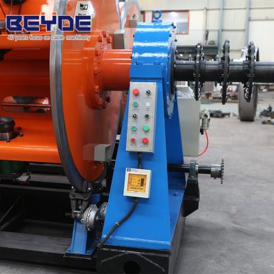
5.2.15. Design principle: Each stranding cage is driven and operated by its own separate motor. The motor and stranding cage reducer box are connected through a coupling to directly drive the hinge cage to operate, providing power for equipment operation and slow positioning. This drive system eliminates the transmission of power through toothed belts and reduces maintenance links. The forward rotation, reverse rotation, neutral gear, start, stop, emergency stop and other operation settings of the stranding cage are all controlled by the electrical system
5.2.16. Structural form: Each section of the stranding cage is an integrated 4-part structure. The stranding cage is supported on the gearbox and front support by two sets of double row self-aligning roller bearings, ensuring the bearing capacity of the cage's axial movement.
5.2.17. Manufacturing process: The front and rear support frames of the entire stranding cage are supported by double supports, with seamless steel pipe support in the middle. The frame body is mainly made by high-strength welding of the steel plate connection surface after processing, and the welded overall frame is subjected to high-temperature annealing in the annealing furnace to accelerate the aging treatment of the deformation and stress generated by the steel plate welding. After 72 hours, it naturally cools to the natural temperature, effectively enhancing the mechanical strength of the entire frame. There is machining allowance for the brake surface of the hinge body, and there is allowance for the top mounting hole. All holes are drilled, milled, and then precision turned on a heavy-duty horizontal lathe at the gantry machining center. The hinge base plate is welded with rectangular tubes, which effectively enhances the stability of the hinge compared to ordinary channel steel base plates and is more suitable for high-speed rotation of the hinge. The dynamic balance experiment after the assembly of the hinge meets the requirements of high-speed and stable operation.
5.2.18. Wire breakage monitoring: The DXJ fully automatic wire breakage detection system is used, and the electrical switch output is precise and reliable. It can stop and brake in a timely manner when the wire is broken or used up, and can prompt on the human-machine operation interface.
5.2.19. After centralized loading bobbin, the pneumatic top needle is used for clamping. After the bobbin is tightened, a separate locking cylinder drives the mechanical stop device to lock the top needle. And the locking status is monitored by the electrical detection device, and the host cannot be started in an unlocked state.
5.2.20. Form of tension for pay-off in the cage: The pay-off in the cage adopts dual tension settings of pneumatic constant tension and mechanical friction tension. The working principle of pneumatic constant tension: From full bobbin to empty, the constant tension output is controlled by PLC, and the tension of the wire is uniform and stable. The tension can be adjusted through the human-machine interface. Equipped with clamp type mechanical tension, it can fine tune the tension of each disc and serve as a backup tension output reserve.
5.2.21. Braking form: The main cage brake adopts a disc shaped flat air brake to reduce the impact of emergency stop inertia on the transmission components. Working principle of overall braking: Coordinated by a programmable logic controller (PLC), the variable frequency motor controller, braking resistor, air pressure proportional valve, etc. jointly complete the slow stop, fast stop, emergency stop and other operations of the entire machine.
5.2.22. Pre-former device: Each section of the host is equipped with a single line pre-former device at the front end. Prefabricate stranded pitch to improve the quality of finished wire. The pre-former device is equipped with a sheet metal safety protective cover, and the operating side of the protective cover is equipped with an acrylic observation window. The cover can be pushed and pulled open, and there is a mechanical locking device.
5.2.23. Stranding cage pass wire form: After the wire inside the cage is released, it passes through the internal guide roller group, wire hole, pre-former device, and distribution board of the twisting body to finally form a cable. The wire passing holes and the dividing plate are internally embedded with alloy wire passing molds, and the inner holes of the wire passing molds are polished.
5.2.24. Safety protection: The cage is equipped with a single side wall type safety protection net, covering the entire machine's cage position at the beginning and end of the operating side. The host protective net is installed using perforated plates or high-density mesh grids supported by columns, and each section of the hinge cage is equipped with a door opening, totaling 3 doors. All three doors of the safety net are equipped with sound and light alarm lights. After opening the door, there is a sound and light alarm prompt. The host control system can choose between two states: A door opening alarm prompt, equipment normal operation, B door opening alarm prompt, and overall braking
5.2.25. Each section of the cage is equipped with an independent air storage tank to ensure gas supply. At the same time, provide a one-time brake air supply for unexpected power outages and other situations.
5.2.26. The front operating position of each section of the e cage is equipped with control buttons such as emergency stop, jog, disconnection control selection, positioning, and up/down panel for easy operation.
5.2.27. The entire machine is operated by a color touch screen with a human-machine interface, and is coordinated and managed by a programmable controller PLC
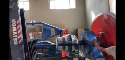
5.3. Automatic load and unload reel device:
5.3.1. Structural form: one column below the side
5.3.2. Drive mode: Hydraulic
5.3.3. Applicable bobbin specification: PND500
5.3.4. The loading bobbin device below the hydraulic side is mainly composed of a wire tray bracket, a linear track, a guide bracket, a transmission oil cylinder, a hydraulic pump station, an electric control system, etc. It can complete actions such as flipping, hanging, positioning, dismounting, and returning in one go.
5.3.5. The hydraulic device adopts a side loading and unloading bobbin form, and after the loading is repositioned, the working table is level with the ground
5.4 Closing wire collect stand
5.4.1. Each section of the stranding cage is equipped with a closing wire mold base, which can complete the wire connection and cable formation or one-time drawing and cabling.
5.4.2. Inner cavity size of wire closing die base: 90x90mm(customized)
5.4.3. Adjustable distance of closing mold base: 300mm
5.4.4 Mould: customer provide
5.5 Concentric type taping machine (note: customer need provide material after order to test)
5.5.1. Tape winding form: concentric type
5.5.2. Max diameter of applicable Tape: Ø500
5.5.3. Applicable tape core diameter: Ø153
5.5.4. Pass wire hole diameter of the taping machine: Φ60
5.5.5. Applicable tape width: 20-50mm
5.5.6. Applicable tape materials: PET/PI/ISOTEX, etc
5.5.7. Break tape detection: photoelectric detection
5.5.8. Taping pitch: 0-100mm (electrically controlled and infinitely adjustable)
5.5.9. Design speed of taping head: 1500r/min
5.5.10. Max operating taping speed: 1000r/min
5.5.11. Fastest production linear speed: 40m/min
5.5.12. Release tension: electromagnetic constant tension
5.5.13. Power of taping motor: 3.0KW (AC variable frequency motor)
5.5.14. Braking form: air brake
5.5.15. Number of storage pads on the rack: ≥ 10 pads
5.5.16. Number of taping machines: The entire machine is equipped with 4 concentric taping machines.
5.5.17. Working mode and structure: The taping machine adopts an all aluminum head, fast opening structure. The tension is provided by electromagnetic tension, and it is output through PLC simulation to maintain uniform unwinding tension. Using an air brake for braking to ensure that the angle is not affected during tape breakage and pads replacement.
5.5.18. Broken tape detection: The taping machine is equipped with a photoelectric broken tape detection system, which can alarm and brake the entire machine when the wrapping tape is used up or broken. The machine is equipped with an alarm prompt light.
5.5.19. Safety protection: The machine is equipped with a sheet metal protective cover, which can be pushed or pulled open on the operating side. After the cover is closed, it can be locked with a mechanical buckle. There is a transparent observation window on the operating side of the shield, and there is an LED working light inside
5.6 Meter counter: (mechanical, digital)
5.6.1 Perimeter of meter wheel: 500mm
5.6.2 Mechanical and digital double show.
5.6.3 With meters correction function, meter counting is accurate and reliable, and meter counting accuracy is ± 0.3%.
5.6.4 Max meter length: 9999mm
5.7 2500kg pneumatic caterpillar
5.7.1. Max traction force: 2500kg
5.7.2. Max passing diameter: Ø100mm
5.7.3. Pairs of traction cylinders: 8 pairs
5.7.4. Traction pitch: 37-1006 (electrically controlled infinitely adjustable)
5.7.5. Max traction linear speed: 60m/min
5.7.6. Traction motor power: 55KW (AC)
5.7.7. Structure and characteristics: Adopting a tracked pneumatic traction machine, the pneumatic tightening and loosening of the cable, the pneumatic tightening of the track, driven by a sub motor, infinitely variable speed, equipped with an air compressor. The braking process of the entire machine is completed through the overall coordination and control of the motor frequency converter, air compressor system, braking resistor, etc. through PLC. The braking of the entire machine is consistent, and the structural strength of the body design is high, making it easy to operate.
5.7.8. Protective device: The pneumatic caterpillar adopts a sheet metal protective cover as a whole, and there is a perforated plate material detachable protective door at the position where the crawler traction passes through the line
5.8 2000mm Portal type take-up with traverse stand
5.8.1. Applicable wire reel range: PN1000-PN2000
5.8.2. Applicable wire reel width: 750-1500mm
5.8.3. Max load capacity: 8T
5.8.4. Traverse wire accuracy: set 1-2% of pitch
5.8.5. Take-up motor: 5.5KW (AC)
5.8.6. Traverse motor power: 1.1kw (AC)
5.8.7. The gantry type collection and discharge line machine is a telescopic tube mounted structure, made of high-quality steel plates and seamless steel pipes. The guide rail runs in the center of the collection line, with a beautiful appearance, convenient operation, and precise action:
5.8.8. The entire machine consists of two ground beams with walking rollers, two columns, sleeve type telescopic beams, wire brackets, and electrical control boxes. The wiring arrangement is of the gantry ground rail walking type, and the clamp sleeve is of the bottom mounted structure.
5.8.9. The two spindle centers on the column are equipped with shaftless loading and unloading wire reels. The centers are driven by two AC motors through a cycloidal pin wheel reducer to drive the screw nut for lifting and lowering. Each center seat can be lifted or lowered separately or simultaneously, and is equipped with mechanical and electrical dual protection devices. In order to meet the needs of different specifications of wire reels, different specifications of centers are equipped.
5.8.10. The sleeve type crossbeam is horizontally moved by an AC motor through synchronous pulleys and friction clutches, driven by screw nuts, for clamping and loosening the wire reel, and equipped with an overload protection device.
5.8.11. The take-up adopts a variable frequency AC motor, which drives the spindle through the K series gearbox to drive the winding reel to rotate, and is equipped with an AC speed controller to control the take-up motor.
5.8.12. The wire traverse mechanism is composed of an AC variable frequency motor, a cycloidal pinwheel gearbox, and a sprocket. The wire arrangement motor is controlled by a frequency converter for speed control, and the wire arrangement pitch is set by the wire arrangement controller. The size of the wire arrangement pitch can be set at any time according to the production process, and the wire arrangement speed automatically tracks the wire collection speed.
5.8.13. The whole machine is equipped with speed, tension and winding pitch adjustment Potentiometer, winding positive and reverse inching button, tension and winding pitch display, winding tension is realized by constant torque mode, and electric control machine is managed by PLC+touch screen
5.9 Electric control system:
5.9.1. The electrical control part is composed of a power cabinet, an operation cabinet, a touch screen, etc., and corresponding control buttons are set in each unit
5.9.2. The electrical cabinet adopts a simulated Rittal control cabinet, which has good mechanical and dust resistance design, and is equipped with an appropriate amount of forced ventilation fans.
5.9.3. Power supply three wire five phase system: 600V, 230V; 60HZ
5.9.4. Control power supply: 24V (DC)
5.9.5. Total installed power: 260kw
5.9.6. Motor protection function: The electrical control circuit design includes protection functions for phase loss, overload, and overheating to prevent motor damage.
5.9.7. Operating system: It can view and modify various parameter settings during the production process in real-time, such as pitch, production speed, current working status, and other information.
5.9.8. Programmable controllers (PLCs) can be connected to Ethernet to view fault information or remotely view and update operating systems.
5.9.9. The unit adopts PLC for unified coordinated control and operation. Using a touch screen human-machine interface for operation. Simple and convenient operation
5.10 Safety protection
5.10.1. Main cage: Wall type door opening protective mesh, perforated plate or high-density mesh grille material. Equipped with an audible and visual alarm that can be linked with the control system.
5.10.2. Taping machine: A sheet metal protective cover with a working light inside. The working side can be pushed or pulled to open, and can be locked with a buckle after closing.
5.10.3.Caterpillar device: The whole adopts a sheet metal protective cover, and the traction track has a protective door made of porous plate material that can be opened downwards at the crossing position.
5.10.4. Coupling, transmission and other parts: sheet metal protective cover
5.10.5 Electrical protection:
A. Main cage disconnection and automatic stop protection
B. Taping machine tape breakage automatic stop protection
C. Automatic locking protection for loading bobbin the main cage
D. Drive motor overload and missing phrase protection
E. Whole machine anti start protection during slow positioning of the loading bobbins
F. Frequency converter fault alarm
G. Insufficient oil supply alarm
6.Operating direction:
Operating direction: Equipment operation direction: Right head machine, facing device operation, left release line, right take-up line, or customized
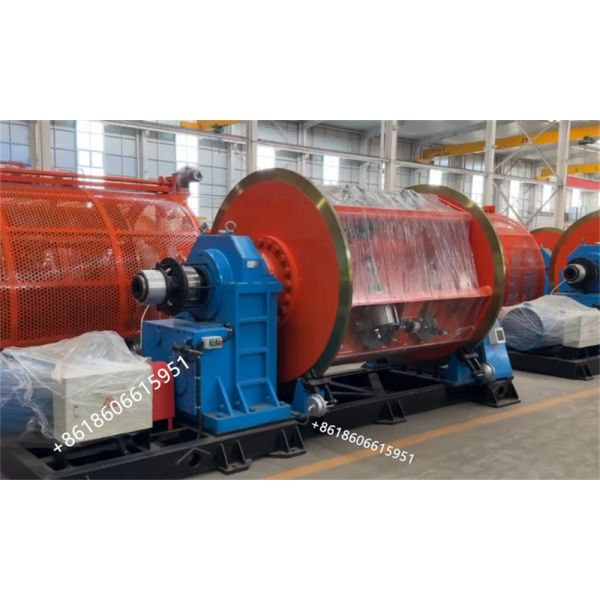
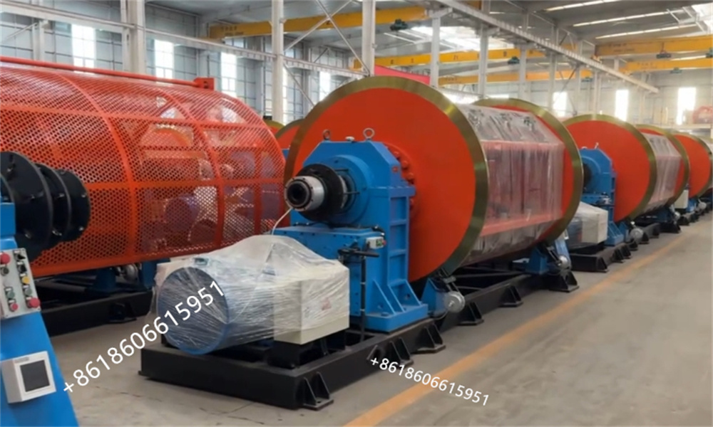
7.Color:
- Rotating part: RAL2004 outer orange yellow
- Equipment main body: 15 external phthalocyanine medium blue
- Transmission protective cover: RAL3020 outer orange red
- Host protective cover: RAL5017 outer middle blue
- Electrical cabinet: RAL7032 egg lime
- Underframe part: RAL9017 outer black
- Other parts/RAL9010 outer white/RAL9017 outer black
-