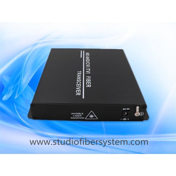
2CH PTZ AHD Fiber Converter also named as 2CH PTZ AHD fiber transmitter and receiver,
which is an universal type supporting 1MP/1.3MP/2MP/3MP/4MP/5MP TVI / CVI /AHD and 1CH Returned RS485 over a single fiber optical fiber , to achieve megapixels level analog HD video point to point highly and reliably transmission over one core multimode or single-mode optical fiber without delay. It also supports the regular analog video format such as PAL / NTSC /SECAM , it is a kind of universal fiber transmission solution for CCTV analog video and data signals . This equipments are available for either standalone or rack-mount installation, which is suitable for different working environment . Electronic and optical adjustments are never required. LED indicators are provided for instantly monitoring system status.
2CH AHD video data to fiber converter Feture:
1, advanced lightning protection design, support 4KV lightning protection;
2, industrial design, SMT process;
3, all-digital optical fiber transmission platform, the same platform multi-service flexible configuration;
4, can provide desktop, centralized card rack two ways;
Independent intellectual property rights large-scale ASIC core;
5, single fiber transmission, optional 20KM, 40KM, 60KM, 80KM, 100KM long-distance transmission.
6, upport 300,000 standard definition video and 1MP, 1.3 MP, 2MP,3MP,4MP,5MP camera 1280X720P/30Hz, 1280PX960P/30Hz, 1920X1080P/30Hz,,2560x1440P/30Hz, 4096x2160P/30Hz resolution analog HD coaxial video, studio-level transmission quality;
7, non-compressed real-time transmission to ensure the best video transmission
2CH AHD to Fiber converter Application:
1. Urban Traffic Monitoring System
2. public security, safe city monitoring system
3. highway security, charging system
4. buildings, campus monitoring network
5. Industrial monitoring (airport, chemical, iron and steel, petroleum, railway, water conservancy, mining, etc.)
6. Military monitoring (storage, frontier defense, guard, national defense, etc.)
7. Power oilfield, television program transmission system
8. Gymnasium (live video, audio transmission)
Specifications
Optics:
Wavelength | 1310nm&1470nm-1610nm |
Output Power | -9~3dBm |
Optic fiber | 50/125u multimode,62.5/125u multimode,9/125u single mode |
Rx sensitivity | -26dBm |
Optical connector | FC(default),ST,SC (selectable) |
Distance | 0~550M (MM) / 0~80KM (SM) (Default distance is 20Km) |
Video:
Number of Channels | 2 |
Input/output impedance | 75 Ohm (unbalance) |
Standard video input/output voltage | 1.0Vp-p |
Video Bandwidth | 50MHz |
Sampling Bandwidth | 8bit |
Sampling Frequency | 108MHz |
Signal to noise ratio | >67dB |
Rise and Fall time | <0.8ns |
Optical Signal Intrinsic Jitter | <0.2 UI |
Differential Gain | < ±1% |
Differential Phase | <±1% |
Connector | BNC |
video pixel | 1280x720@25,30,50Hz/1MPX 1280x960@25,30Hz/1.3MPX 1920x1080@30Hz/2MPX 2560x1440@30Hz/3MPX 4096x2160@30Hz/5MPX |
Data:
Protocol | Default :RS485 (RS232/RS422 selectable) |
Number of channels | 1 |
Connector | 3pins Terminal Blocks |
Data Rate | 0-200Kbps |
Directions | Default :Simplex from Rx to Tx (BIDI duplex selectable) |
Mechanical Structure & Environment
Power | DC5V 2A |
Power Consumption | ≤6W |
Working Temperature | -15ºC ~65ºC |
Storage Temperature | -40ºC ~85ºC |
Relative Humidity | 5%~95% ( no condensation) |
MTBF | ≥ 100000Hours |
Dimension For The Converter(TX&RX) | 167x173x28MM |
Dimension For The Package of 1 Pair | 328x220x103MM |
Net Weight | 1KG |
Gross Weight | 1.25KG |
Standalone Dimensions:
Interface introduction and LED indication function
The front panel of the transmitter & receiver has 2 BNC connector, 4 green indicators, and one data interface (pure video optical transceivers do not have this connector), as shown in the following figure:
The front panel interface is:
1, fiber interface;
2, BNC video interface (BNC video1&vedio3 interface on the transmitter for the video input, connected to the video port, the corresponding LED1&LED3 indicator will light up. BNC video interface on the receiver for the video output interface, used to connect video recorders or other display devices);
3, data interface (Terminal Blocks,the PIN5 , PIN6,PIN7 connected to the video recorder or camera 485 data port)
The transmitter & receiver has a grounding hole on the back panel and a power supply DC block connector, as shown in the following figure
The interfaces on the rear panel are: grounding holes for connecting and releasing ground to achieve better lightning protection and anti-static effects; and a power interface for connecting an external power adapter.
LED Indicator Description
PWR --power indicator
FIBER-- fiber connection indicator
LED1-- video interface indicator
Connection Diagram: