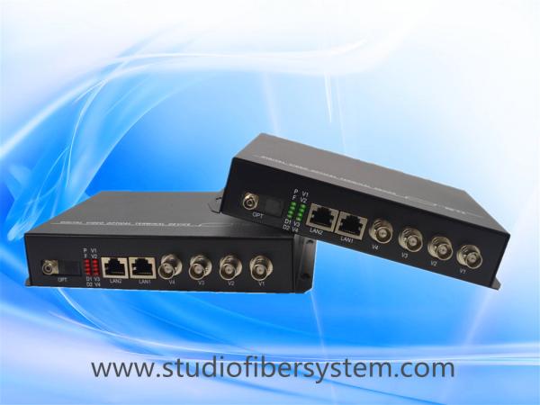
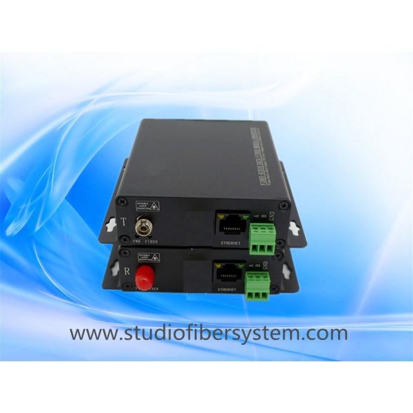
Video+Audio+Contact Closure+ Data+Ethernet+Telephone To Fiber Multiplexer
The Video Fiber Multiplexer adopts international advanced digital optical fiber transmission technology to realize 4ch analog video,2ch bidirectional 485/232 data signals, 2ch 100M ethernet signal, 4ch bidirectional analog audio,2ch bidirectional contact closure and 2ch pcm telephone synchronous distortion-free, high quality transmission over fiber. It uses all-digitally uncompressed video transmission technology to meet the multi-functional needs of users, and the installation is simple and easy. Its optical module and core circuit are imported components, performance stability, suitable for different working environments.
Features
1, independent structure, suitable for centralized management of 4U racks;
2, uncompressed, real-time signal transmission;
3, Gigabit fiber transmission, large capacity, easy to upgrade;
4, advanced circuit design to ensure the reliability, consistency and stability of the equipment;
5, LED status indication, real-time monitoring of the operating status of the system;
6, support single mode or multimode fiber transmission;
7, FC / SC / ST fiber interface sectable;
8, single mode maximum transmission distance up to 120KM
Specifications
Product Name :Video+Audio+Contact Closure+Data+Ethernet+Telephone To Fiber Multiplexer | ||
Functions:4ch analog video+4Bidi Audio+2Bidi RS232/485+2ch 100M Ethernet+2Bidi Contact Closure+2Telephone | ||
Fiber | Fiber interface | FC/SC/ST |
Wavelength | Multimode (850nm); single mode (1310nm, 1550nm) | |
Transmit power | -9.5~-3dBm average optical power 850nm | |
Light receiving sensitivity | -15dBm average optical power 850nm | |
Transmission distance | 1m ~ 2000m multimode fiber,1m to 20km single mode fiber | |
Video | Physical Interface | 4xBNC |
Input/Output Impedance | 75Ω (unbalance) | |
Video Format | PAL/NTSC/SECAM automatically compatible | |
Video bandwidth | 8MHz | |
Video sampling | 20MHz high speed sampling | |
Differential gain | DG <1% (typical) | |
Differential phase | DP <0.7° (typical) | |
Audio | Support audio format | DTS-HD/Dolby-true HD/LPCM7.1/DTS/Dolby-AC3/DSD |
Audio signal format | Unbalanced line audio default | |
Input/output Impedance | 600Ohm(unbalance) | |
Max input/output voltage | 2.0Vp-p | |
Frequency Response | 10~20kHz | |
SNR | >95dB | |
Connector | Standard Terminal Block | |
Data | Data Protocol | RS232/RS485 |
Data Rate | 0~384 Kbps | |
Error Rate | < 10-9 | |
Connector | Standard Terminal Block | |
Contact Closure | Signal input/output | alarm,TTL or passive dry Contact Closure |
Connector | Standard Terminal Block | |
Ethernet | Work mode | Full duplex/half duplex |
Data Rate | 2x RJ45, 10/100Mbps(AUTO) | |
Standard | IEEE802.3 10Base IEEE802.3u 100Base | |
IEEE802.3ab 1000Bas IEEE802.3z 1000Base | ||
Telephone | Description | FXO/FXS Ordinary telephone |
Telephone Ports | 2xTerminal Block | |
Switch Terminal | Ordinary telephone or PBX, PBX (PBX), public telephone outside the PSTN | |
FXS | Ringing voltage: 75V, ringing frequency: 25HZ | |
FXO | Second line input impedance:600Ω (hook), return loss: 40db, ring detection voltage:35V | |
Ring detection frequency | 17HZ-60HZ, second-line input impedance: 600Ω (hook), return loss: 40 db | |
Broadband Voice | 8KHZ | |
Connection | Point to point, telephone to telephone, telephone to switch | |
Code | PCM code | |
General | Power supply | 5VDC |
Power consumption | <10W | |
Operating temperature | 0~55°C | |
storage temperature | -20 to 70 ° C | |
Humidity (no condensation) | 0 to 95% | |
Dimension | 185x137x35mm | |
Package Size | 33x19x9CM | |
material | Iron | |
colour | black | |
Net Weight | 1.1Kg/pair | |
Gross Weight | 1.5Kg/pair | |
MTBF | >30000hour |
More Details:
Package list
Fiber transmitter --1 pcs; fiber receiver --1 pcs; Power adapter --2 pcs; User manual--1 pcs
Installation
1. Connect the Video/Audio/data/ ethernet signal source to the fiber transmitter.
2. Connect the receiver end to the display device (such as HDTV, splicing screen, etc.).
3. Connect the fiber between the transmitter end and the receiver end.
4. Connect the transmitter and receiver to the power supply. When the indicator light is on, the system runs normally.
Connection Diagram