GH Series Flexible Shaft Coupling Oldham Coupling
Structure of Oldham Coupling :
Oldham couplings are a three-piece assembly with a balanced design comprised of two hubs and a center disk. This allows for a highly customizable coupling that allows the user to combine clamp and set screw hubs with inch, metric, keyed, and keyless bores in sizes ranging from 1/8” to 1-1/8” and 3mm to 30mm. The center disk is available in three materials to allow designers to fit the coupling to their application requirements. While oldham couplings can accommodate small amounts of angular and axial misalignment, they are especially useful in parallel misalignment accommodating up to 10% of their OD in misalignment. All oldham couplings are carefully made under strict quality controls .
The material of the oldham couplings parts can be 45 steel, and the working surface needs to be heat treated to improve its hardness; Q275 steel can also be used for lower requirements without heat treatment. In order to reduce friction and wear, the oil hole in the middle plate should be lubricated with oil.
Unlike other Flexible Shaft couplings, the oldham couplings does not have an elastic element that works like a spring, so the oldham couplings will not increase the bearing load because of the increase in relative displacement between shafts. In any case, this series of couplings is more than good value for money, the ability to choose different materials of the slider is an advantage of this coupling.
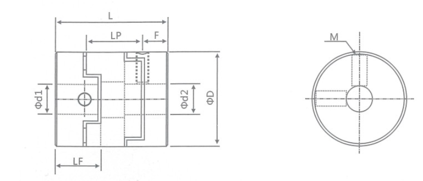
Specification of Oldham Coupling:
model parameter | common bore diameter d1,d2 | ΦD | L | LF | LP | F | M | tightening screw torque (N.M) |
GH-16X18 | 4,5,6,6.35,7,8 | 16 | 18 | 7.1 | 11.6 | 3.55 | M3 | 0.7 |
GH-20X25 | 5,6,6.35,7,8,9,9.525 | 20 | 25 | 9.1 | 12.7 | 4.55 | M4 | 1.7 |
GH-25X28 | 5,6,6.35,8,9,9.525,10,11,12,14 | 25 | 28 | 11.7 | 16.65 | 5.58 | M4 | 1.7 |
GH-32x33 | 5,6,8,9,9.525,10,11,12,12.7,14,15,16 | 32 | 33 | 14 | 19.5 | 7 | M4 | 1.7 |
GH-40X35 | 8,9,9.525,10,11,12,12.7,14,14,16,17,18,19,20 | 40 | 35 | 15.5 | 18.4 | 7.75 | M4 | 1.7 |
GH-45X46 | 8,9,9.525,10,11,12.7,14,15,16,17,18,19,20,22 | 45 | 46 | 21.5 | 18.4 | 9 | M5 | 4 |
GH-50X38 | 10,12,12.7,14,15,16,17,18,19,20,22,24,25 | 50 | 38 | 16.5 | 15 | 8.25 | M5 | 4 |
GH-55X57 | 10,12,12.7,14,15,16,17,18,19,20,22,24,25,28,30,32 | 55 | 57 | 27 | 17.5 | 10.5 | M5 | 4 |
GH-63X47 | 14,15,16,17,18,19,20,22,24,25,28,30,32 | 63 | 47 | 21 | 17.5 | 10.5 | M6 | 8.4 |
GH-70X77 | 16,17,18,19,20,22,24,25,28,30,32,38,40 | 70 | 77 | 36.5 | 25 | 13.5 | M8 | 10.5
|
model parameter | Rated torque (N.M)* | allowable eccentricity (mm)* | allowable deflection angle (°)* | allowable axial deviation (mm)* | maximum speed rpm | static torsional stiffness (N.M/rad) | moment of inertia (Kg.M2) | Material of shaft sleeve | Material of shrapnel | surface treatment | weight (g) |
GH-16X18 | 0.7 | 0.8 | 3 | ±0.2 | 9000 | 30 | 3.3x10⁻⁷ | High strength aluminum alloy | P A 6 6 | Anodizing treatment | 6 |
GH-20X25 | 1.2 | 1.2 | 3 | ±0.2 | 7000 | 58 | 1.1x10⁻⁶ | 18 | |||
GH-25X28 | 2 | 1.6 | 3 | ±0.2 | 6000 | 130 | 3.1x10⁻⁶ | 25 | |||
GH-32x33 | 4.5 | 2 | 3 | ±0.2 | 4800 | 270 | 9.6x10⁻⁶ | 44 | |||
GH-40X35 | 9 | 2.4 | 3 | ±0.2 | 3600 | 520 | 2.3x10⁻⁵ | 81 | |||
GH-45X46 | 12 | 2.8 | 3 | ±0.2 | 3500 | 560 | 3.8x10⁻⁵ | 136 | |||
GH-50X38 | 19 | 2.6 | 3 | ±0.2 | 3000 | 800 | 1.8x10⁻⁴ | 142 | |||
GH-55X57 | 22 | 3.3 | 3 | ±0.2 | 2800 | 795 | 8.0x10⁻⁴ | 255 | |||
GH-63X47 | 19 | 3 | 3 | ±0.2 | 2500 | 1200 | 8.3x10⁻⁴ | 320 | |||
GH-70X77 | 56 | 3.8 | 3 | ±0.2 | 2500 | 1260 | 3.9x10⁻⁴ | 445 |
Pictures of Oldham Coupling