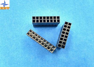
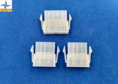
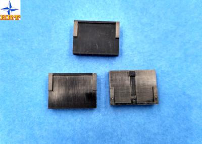
1, Detailed part information as below
Basic size information | |||
Circuits | 2 to 12 positions | ||
Pitch | 3.0mm | ||
Mating lock | Yes, with | ||
Panel Mount | No | ||
Glow-Wire Complian | No | ||
Insulation O.D. | 1.85mm(Max) | ||
Matched termial materials | phosphor bronze | ||
Finish terminal | Tin-plated or gold-flash | ||
Electrical properties | |||
Current Rating | 5A AC, DC | ||
Voltage Rating | 250V AC, DC | ||
Contact Resistance | 10mΩ Max | ||
Insulation Resistance | 1000MΩ min | ||
Withstanding Voltage | 1500V AC/minute | ||
Mechanical properties | |||
Temperature range | -25℃ to 85 ℃ | ||
Terminal Insertion Force | 1.50kgf (Max.) | ||
Terminal/Housing Retention Force | 2.50kgf (Min.) | ||
Pin Retention Force | 1.50kgf (Min.) | ||
Latch Yield Strength | 7.00kgf (Min.) | ||
Other information please kindly check the following picture. |
2, Corresponding engineering drawing & testing report
Actuator Insertion/Withdrawal Force
[Unit : kgf]
Circuits | At Initial | Circuits | At Initial | ||
Insertion (Max.) | Withdrawal (Min.) | Insertion (Max.) | Withdrawal (Min.) | ||
Single | 0.50 | 0.20 | 10 | 6.80 | 2.35 |
02 | 1.20 | 0.35 | 11 | 7.50 | 2.60 |
03 | 1.90 | 0.60 | 12 | 8.20 | 2.85 |
04 | 2.60 | 0.85 | 14 | 9.60 | 3.35 |
05 | 3.30 | 1.10 | 16 | 11.00 | 3.85 |
06 | 4.00 | 1.35 | 18 | 12.40 | 4.35 |
07 | 4.70 | 1.60 | 20 | 13.80 | 4.85 |
08 | 5.40 | 1.85 | 22 | 15.20 | 5.35 |
09 | 6.10 | 2.10 | 24 | 16.60 | 5.85 |
Mechanical Performance
Test Description | Procedure | Requirement | ||
5-1 | Actuator Insertion & Withdrawal Force | Insert and withdraw connectors at the speed rate of 25±3mm / minute. | Refer to paragraph 7 | |
5-2 | Crimping Pull Out Force | Fix the crimped terminal, apply axial pull out force on the wire at the speed rat of 25±3mm / minute.(Based upon JIS C5402 6.8) | AWG#20 | 6.0kgf (Min.) |
AWG#22 | 4.0kgf (Min.) | |||
AWG#24 | 3.0kgf (Min.) | |||
5-3 | Terminal Insertion Force. | Insert the crimped terminal into the housing. | 1.50kgf (Max.) | |
5-4 | Terminal/Housing Retention Force. | Apply axial pull out force at the speed rate of 25±3mm / minute on the terminal assembled in the housing. | 2.50kgf (Min.) | |
5-5 | Pin Retention Force | Apply axial push force at the speed rate of 25±3mm / minute | 1.50kgf (Min.) | |
5-6 | Latch Yield Strength |
Mate connectors and pull apart until both latches break at the speed rate of 25±3mm / minute |
7.00kgf (Min.) | |
5-7 | Panel Mount Retention Force | Insert the housing into panel cut out, barbs break at the speed rate of 25±3mm / minute. |
Single Row(W-W) 8.0kgf (Min.) Dual Row(W-W) 16.0kgf (Min.) |
|
5-8 | Durability | When mated up to 50 cycles repeatedly by the rate of 10 cycle per minute. | Contact Resistance 20mΩ (Max.) | |
5-9 | Vibration |
Amplitude: 1.5mm P-P Sweep time: 10-55-10 Hz in 1 minute Duration: 2 hours in each X.Y.Z. axes. (Based upon MIL-STD-202 Method 201A) |
Appearance No Damage. Contact Resistance 20mΩ (Max.) Discontinuity 1 μsec.(Max.) |
|
5-10 | Physical Shock | 490m/s²{50G},3 strokes in each X.Y.Z. axes. (Based upon JIS C0041/MIL-STD-202 Method 213B Cond. A) |