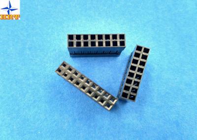
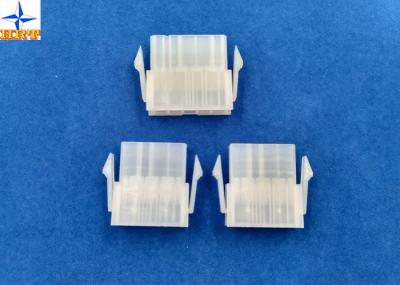
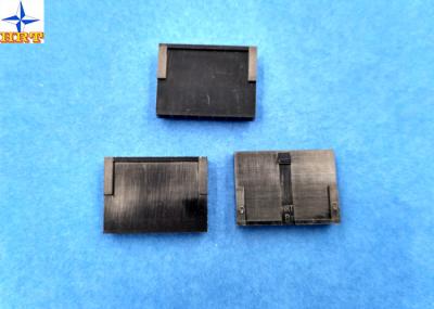
Power cable connectors pitch 2.54mm wire to board PA66 Housing / Terminal
Description:
1, A2540series Housing have A2540H-NP .
2, Housing used materials: PA66, Halogen Free , Fire-protection rating is UL 94-V0. Minimum packing quantity is 1000pcs/bag.
3. Terminals are stamped by Brass , E-Stamping before Tin-plated ,Tin-plated we calling A2540-TPe, , Minimum packing quantity is 20,000pcs/Reel. The daily production capacity is 300 to 400 KPCS.
4. Terminals' wire range :AWG #22--#28,insulation OD is1.70mm(Max).
Specifications:
Test Description | Procedure | Requirement |
Contact Resistance | Mate connectors, measure by dry circuit, 20mV max., 10mA.(Based upon JIS C5402 5.4) | 10mΩ (Max.) |
Insulation Resistance | Mate connectors, apply 500V DC between adjacent terminal or ground. (Based upon JIS C5402 5.2/MIL-STD-202 Method 302 Cond. B) | 1000MΩ (Min.) |
Dielectric Withstanding Voltage | Mate connectors, apply 1000V AC (rms) for 1 minute between adjacent terminal or ground. (Based upon JIS C5402 5.1/MIL-STD-202 Method 301) | No Breakdown. |
Contact Resistance on Crimped Portion | Crimp the applicable wire on to the terminal, measure by dry circuit, 20mV (Max.)., 10mA.. | 5mΩ (Max.) |
Voltage rated | 250V AC ,DC |
Current rated | 3A AC,DC |
Withstand voltage | 800VAC/minute |
Insulation resistance | 500MΩ Min |
Contact resistance | 10mΩ Max |
Operating temperature | -25°C~85°C |
Testing report
Mechanical Performance
Test Description | Procedure | Requirement | ||
5-1 | Actuator Insertion & Withdrawal Force | Insert and withdraw actuator at the speed rate of 25±3mm / minute. | Refer to paragraph 7-2 | |
5-2 | Crimping Pull Out Force | Fix the crimped terminal, apply axial pull out force on the wire at the speed rat of 25±3mm / minute.(Based upon JIS C5402 6.8) | AWG#22 | 4.0 kgf (Min.) |
AWG#24 | 3.0 kgf (Min.) | |||
AWG#26 | 2.0 kgf (Min.) | |||
AWG#28 | 1.0 kgf (Min.) | |||
5-3 | Terminal Insertion Force. | Insert the crimped terminal into the housing. | 1.50 kgf (Max.) | |
5-4 | Terminal/Housing Retention Force. | Apply axial pull out force at the speed rate of 25±3mm / minute on the terminal assembled in the housing. | 2.00 kgf (Min.) | |
5-5 | Pin Retention Force | Apply axial pull out force at the speed rate of 25±3mm / minute. | 2.00 kgf (Min.) | |
5-6 | Durability | When mated up to 50 cycles repeatedly by the rate of 10 cycle per minute. | Contact Resistance 20mΩ (Max.) | |
5-7 | Vibration | Amplitude: 1.5mm P-P Sweep time: 10-55-10 Hz in 1 minute Duration: 2 hours in each X.Y.Z. axes. (Based upon MIL-STD-202 Method 201A) | Appearance No Damage. Contact Resistance 20mΩ (Max.) Discontinuity 1 μsec.(Max.) | |
5-8 | Physical Shock | 490m/s²{50G},3 strokes in each X.Y.Z. axes. (Based upon JIS C0041/MIL-STD-202 Method 213B Cond. A) |
Crimp Specifications & Actuator Insertion/Withdrawal Force
7-1 Terminals with height, suggestion pressure width and wire and terminal's retention
Wire Diameter | Numbers | Conductor Parts(Core Wire)mm | Insulation Parts(PVC)mm | ||
Width | Height | Width | Height | ||
AWG#22 | A2540 | 1.30±0.10 | 0.70~0.85 | 1.75(Max.) | 1.60(Max.) |
AWG#24 | |||||
AWG#26 | |||||
AWG#28 |
7-2 [Unit : kgf]
Circuits | At Initial | Circuits | At Initial | ||
Insertion (Max.) | Withdrawal (Min.) | Insertion (Max.) | Withdrawal (Min.) | ||
Single | 0.60 | 0.10 | 09 | 7.00 | 2.00 |
02 | 2.00 | 0.80 | 10 | 7.00 | 2.00 |
03 | 2.50 | 0.80 | 11 | 7.50 | 2.00 |
04 | 3.00 | 1.00 | 12 | 7.50 | 2.00 |
05 | 4.00 | 1.50 | 13 | 8.00 | 2.50 |
06 | 5.00 | 1.50 | 14 | 8.00 | 2.50 |
07 | 5.50 | 1.50 | 15 | 8.50 | 2.50 |
08 | 6.50 | 1.50 |