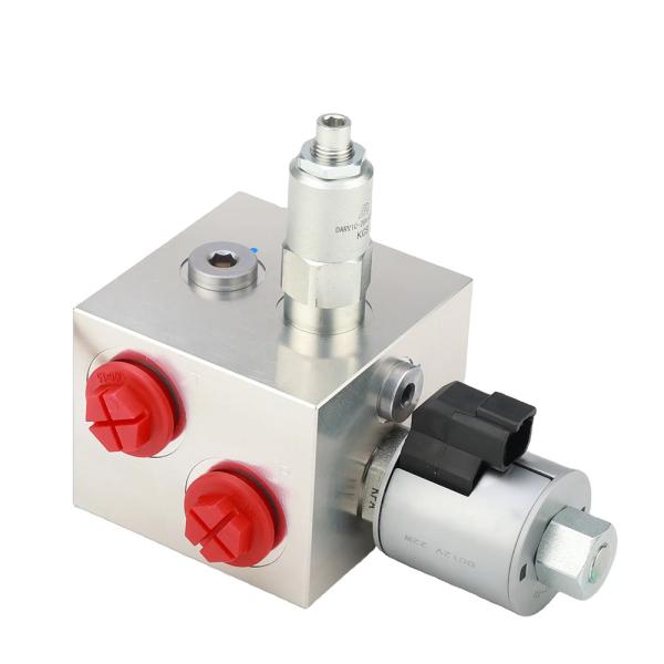
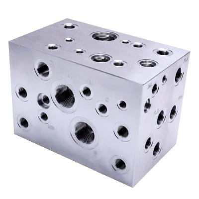
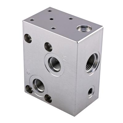
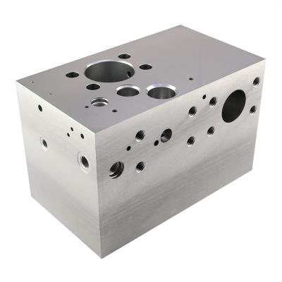
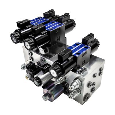
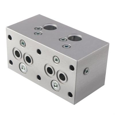
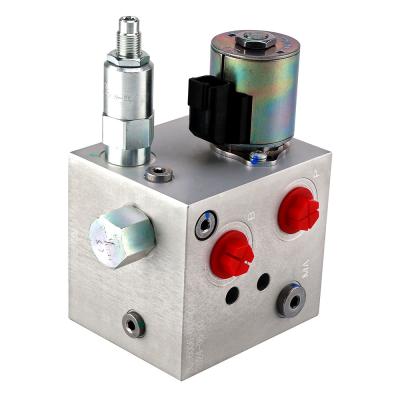
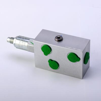
Hydraulic Valve Block 12V Solenoid Valve Aluminum Hydraulic CNC Processing Service
A hydraulic valve block is a component used in a hydraulic system to control the pressure, flow, and direction of a fluid (usually hydraulic oil). It is usually composed of multiple valve bodies, valve cores, springs, and other auxiliary components. Here is the basic working principle of a hydraulic valve block:
Valve body: The valve body is the basic structure of the valve block, and it has multiple channels inside to guide the flow of hydraulic oil.
Valve core: The valve core is the moving part in the valve block, which usually matches the shape of the channels inside the valve body. The position of the valve core determines the flow path of the hydraulic oil.
Here are several common hydraulic valves and their working principles:
1. Directional control valve
Directional control valves are used to control the direction of hydraulic oil flow.
Working principle: The path of hydraulic oil flow is changed by moving the valve core. For example, in a four-way valve, the position of the valve core can make the hydraulic oil flow to one end or the other end of the hydraulic cylinder, thereby extending or retracting the piston.
2. Pressure control valve
Pressure control valves are used to regulate or limit the pressure in the system.
Working principle: This type of valve usually contains a spring and a valve core. When the system pressure reaches the set value, the hydraulic oil will push the valve core open, balancing the spring force, allowing part of the oil to flow back to the tank or bypass, keeping the system pressure stable.
3. Flow control valve
The flow control valve is used to adjust the flow of hydraulic oil through the valve.
Working principle: The flow is controlled by adjusting the size of the throttle on the valve core. The smaller the throttle, the less flow passes; the larger the throttle, the more flow.
4. Reversing valve
The reversing valve is used to change the flow direction of the oil in the hydraulic system.
Working principle: By manipulating the position of the valve core, the inflow and outflow ports of the oil are changed, thereby changing the movement direction of the actuator (such as a hydraulic cylinder or hydraulic motor).
Comprehensive working principle
When the hydraulic oil enters the valve block from the inlet, it is directed to different channels according to the position of the valve core.
The position of the valve core is usually determined by an external control signal, such as an electromagnet, a manual joystick, a hydraulic or pneumatic signal.
When the control signal acts on the valve core, the valve core moves, thereby opening or closing a specific oil circuit to achieve various functions of the hydraulic system.
The design of the hydraulic valve block enables it to integrate multiple functions, reduce connection points and leakage points, and improve system reliability and efficiency. By precisely controlling the flow of hydraulic oil, the hydraulic valve block plays a vital role in the hydraulic system.
High Quality CNC OEM Machining supplier | ||||
Service | CNC Turning, CNC Miling, Laser Cutting, Bending | |||
Materials | Aluminum: 2000 series,6000 series,7075,etc | |||
Stainlesss steel: Sus303,SUs304,$$316,$S316L.17-4PH etc | ||||
Steel: 1214L/121511045/4140/SCM440/40CrMo | ||||
Brass: 260,C360,H59,H60,H62,H63,H65,H68,H70,Bronze,Copper | ||||
Titanium: GradeF1-F5 | ||||
Plastic: POM/PA/PC/PMMA /PVC/PU/Acrylic/ABS/PEEK etc | ||||
Surface Treatment | Anodize, Bead blasted, Silk Screen, PVD Plating, Zinc/Nickl /Chrome/Titanium PlatingBrushing,Painting, Powder Coated, Passivation,Electrophoresis, Electro Polishing. Knurl, etc | |||
Tolerance | +/-0.002~+/-0.005mm | |||
Surface Roughness | Min Ra0.1~3.2 | |||
Drawing Accepted | Stp,Step,lgs,Xt,AutoCAD(DXF,DWG), PDF, | |||
Lead Time | 1-2 weeks for samples,4-5 weeks for mass production | |||
Quality Assurance | IS09001:2015,ROHS, TUV | |||
Payment Terms | Trade Assurance, TT/Paypal/WestUnion |