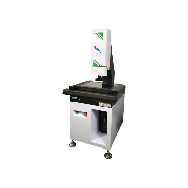
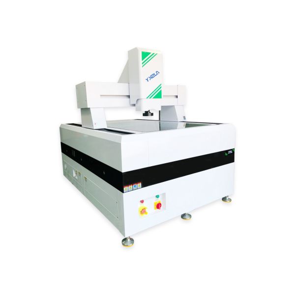
Automatic Control CNC Vision Measuring System 0.001mm Raster Resolution
Mechanism and Application Characteristics of Coordinate measuring machine:
1. Movement of Mechanism:
This measuring instrument is provided with tri-axial automatic control and equipped with Sinpo precision grating system, high-efficiency motor system, high-standard and high-precision V-type guide rail as well as professional measuring software for measurement.
2. Merits with the non-contact auto-measuring instrument:
This instrument can avoid human error of the “Object Work Piece” as caused by manual measuring, and can as well avoid secondary damage caused to “Object Work Piece” by manual measuring, with ensured mass stability and criteria consistency of the object work piece. This instrument can enhance multi-fold the detecting efficiency in the production process, identify the defects and control over non-yields beforehand in production process, and can meanwhile help lower part of the costs spent on manual detection, and increase the timeliness of product delivery.
3. Applicable scope:
This measuring instrument can be used for dimensional accuracy measurement of various molds, aircraft, automobile, mobile phone, computer, metals and hardware, plastics, electronics, die-cutting, screen printing and stencil, LCP film, PCB board, FPC, LCDTFT, glass cover-plate, TP, and frame of ultra-large LCD, as well as for auxiliary measurements such as 2D and 3D measuring as needed in reverse engineering, graphic R&D, design, plotting and editing, and laboratory, etc.
4. Main functional configurations of instrument:
This instrument is used in coupling with dedicated image measuring software, high-definition color 650TV CCD, high resolution of 0.7–4.5 folds (special high-definition zoom and fixed-focus screen optical lens), dedicated computer, LCD, keyboard, mouse (optional) and digital measurement.
Technical parameters
Paramter and Model |
AMQ540 |
|
Workbench |
Platfom size(mm) |
720X620 |
Glass table size(mm) |
550X450 |
|
Load-bearing weight(kg) |
20 |
|
Travel |
X axis(mm) |
500 |
Y axis(mm) |
400 |
|
Z axis(mm) |
200 |
|
Image and measurement system |
Display resolution(mm) |
1/0.5(Optional) |
Instrument precision(um) |
(3+L/200)um |
|
Imaging system(CCD) |
HD color |
|
Zoom objective(X) |
Zoom objective 0.7~4.5X |
|
Total video magnification(x) |
30~190X |
|
Working distance(mm) |
96mm |
|
Light source |
LED programmable partiton light source(Coaxial light source optional) |
|
Outline dimension(mm) |
1090X820X1700 |
|
Weight(kg) |
550kg |
|
Power supply |
220V AC 50Hz |
Configuration List:
Sequence number |
Name |
Unit |
Quantity |
1 |
Main body |
PCS |
1 |
2 |
Instrument table |
PCS |
1 |
3 |
AUSKY software |
PCS |
1 |
4 |
video card |
PCS |
1 |
5 |
Joystick |
PCS |
1 |
6 |
Dongle |
PCS |
1 |
7 |
Computer |
PCS |
1 |
8 |
Liquid crystal display |
PCS |
1 |
9 |
Aocheng optical calibration block |
PCS |
1 |
10 |
Precision probe(optional) |
PCS |
1 |
11 |
Keyboard and mouse |
PCS |
1 |
12 |
Specification warranty card certificate |
PCS |
1 |
Introduction to the software functions:
Software interface
A. Multiple measuring methods, including auto edge-tracing, auto sectional edge-tracing, mouse on-screen point fetch, crossline pointing, proximity pointing, contrast and pinnacle pointing, contour pointing, probe pointing, laser pointing, and etc.
B. Red out-of-tolerance warning
In case of out-of-tolerance of the measuring result, the specific element and item of element can be displayed, and the
derived EXCEL may the same prompt which item is out of the tolerance.
C. Ample functions of the image window
Can display magnification ratio and scale, and can do simple distance and angle measuring
D. Ample functions of coordinate system
Can establish multiple coordinate systems on the basis of the actual circumstance, can switch flexibly data under all
coordinate systems, can achieve conveniently switchover between straight angle coordinate system and polar coordinate
system, can achieve the save and call-out of different coordinate system, and can display different modes of coordinate system.
E. Laser measuring
Laser measuring sees an increasing popularity in imaging device measuring. Our software is also improved and
optimized responding to the measuring call. We herein introduce as below:
F. Connection and interfacing with laser
Currently, our measuring device can connect with laser of following brands: Keyence, Panasonic, Omron, Miyi, Stil,
ERT, Sunny, and etc. Select the laser and COM you wish to connect with in the Laser List in the Parameter Setting.
(After connection, the measuring method using laser measuring is indicated as below(L: Reading of the line is the
current laser reading, and corresponding interface of laser measuring will also pop up in the Graphic Zone)
G. Synchronization of laser and image
Before laser measuring, first to synchronize the laser and image, before following measuring can be performed. Using a
sample, find a cusp on the picture, before shift the crossline center to such cusp to call out the coordinate value, before
shift the laser spot to such cusp to call out the coordinate value of such cusp, click to confirm to wrap up the
synchronization, to achieve the image programming laser measuring.
(With this, in subsequent measuring process, whatever laser spot mining or imaging spot mining, they can be shifted to
the element center already mined)