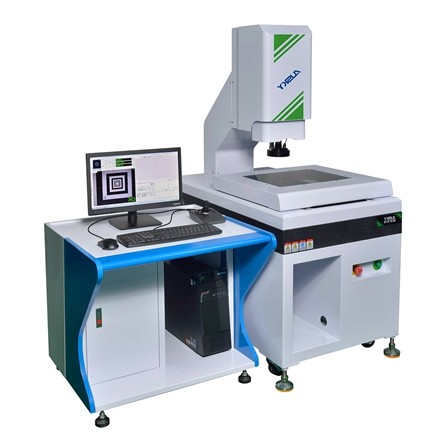
Electronic Optical Coordinate Measuring Machine For Industrial Inspection
Introduction of Coordinate Measuring Machine
Applied mainly for 2D measurement and can support some specific 3D measurement as necessary, this instrument is a high precision and high efficiency measuring machine. Designed and manufactured by Aocheng TECHNOLOGY, a company with more than 15 years of history in precision measuring systems, AUSKY Video measuring machines are of good quality and reliability and have been used in the field of machinery, electronics, instrument, meter, watch, light industry, plastics as well as measuring chambers, laboratories of institutes and universities, research institutes, metrological verification departments and workshops, etc.
Technical parameters
Paramter and Model | AQC320 | |
Workbench | Platfom size(mm) | 460*360 |
Glass table size(mm) | 350X250 | |
Bearing(kg) | 20 | |
Travel | X axis(mm) | 300 |
Y axis(mm) | 200 | |
Z axis(mm) | 200 | |
Image and measurement system | Display resolution(mm) | 1/0.5(Optional) |
Instrument precision(um) | (3+L/200)um | |
Imaging system(CCD) | HD color 650TV | |
Zoom objective(X) | Zoom objective 0.7~4.5X | |
Total video magnification(x) | 30~190X | |
Working distance(mm) | 96mm | |
Light source | LED programmable partiton light source(Coaxial light source optional) | |
Outline dimension(mm) | 740X660X970 | |
Weight(kg) | 250kg | |
Power supply | 220V AC 50Hz |
Configuration List:
Sequence number | Name | Unit | Quantity |
1 | Main body | PCS | 1 |
2 | Instrument table | PCS | 1 |
3 | AUSKY software | PCS | 1 |
4 | video card | PCS | 1 |
5 | Dongle | PCS | 1 |
6 | Computer | PCS | 1 |
7 | Liquid crystal display | PCS | 1 |
8 | Aocheng optical calibration block | PCS | 1 |
9 | Keyboard and mouse | PCS | 1 |
10 | Specification warranty card certificate | PCS | 1 |
Introduction to the software functions:
Software interface
A. Multiple measuring methods, including auto edge-tracing, auto sectional edge-tracing, mouse on-screen point fetch, crossline pointing, proximity pointing, contrast and pinnacle pointing, contour pointing, probe pointing, laser pointing, and etc.
B. Powerful edge-tracing algorithm ensures sampling point accuracy and automatic pixel correction on sampling stability,
where, one stroke will enable automatic pixel correction, needless to shift frequently.
C. Element construction
Element structure technique, offers multiple methods, such as shifting, rotating, extracting, combining, paralleling,
plumbing, mirroring, symmetry, intersecting, tangentially structured elements; Element structure will enable user to
tackle some elements hard to measure, and consequently resulting in increased working efficiency; The compositional
process is to select elements for compositional involvement, select the result element, clear and simple. Options for
composition methods available in form of illustration.
D. Ample report functions
Result data export toolbar
The software supports the EXCEL, WORD, TXT, DXF, IGS format document exporting. The EXCEL or WORD
applications must be installed before you export the EXCEL or WORD documents. Click the EXCEL and WORD
exporting button will automatically start the corresponding application. The DXF format documents is opened with
AutoCAD or the other graphics software. The document exporting toolbar is as follows:
The user can set whether to export the measurement results of an element, and can also set whether to export one item of
an element results, as shown below:
(2) The EXCEL document export settings
Because of the diversification of the EXCEL table requirements, the software support the EXCEL document settings,
click the EXCEL export settings button on the export toolbar and pop up the following dialog box.
E. Red out-of-tolerance warning
In case of out-of-tolerance of the measuring result, the specific element and item of element can be displayed, and the
derived EXCEL may the same prompt which item is out of the tolerance.
F. Ample functions of the image window
Can display magnification ratio and scale, and can do simple distance and angle measuring
G. Ample functions of coordinate system
Can establish multiple coordinate systems on the basis of the actual circumstance, can switch flexibly data under all
coordinate systems, can achieve conveniently switchover between straight angle coordinate system and polar coordinate
system, can achieve the save and call-out of different coordinate system, and can display different modes of coordinate system.
H. Convenient program editing and modifying
Enable to modify conveniently light source data, kinetic data, focusing data, program location, measuring height, and
etc., as well as can replace existing elements with new elements.
I Ample tolerance functions
Multiple calculations of size and geometric tolerance available; Allowable for calculating 2D and 3D tolerance, e.g,
geometric tolerance as roundness, cylindricity, linearity, planeness, etc., as well as tolerances as location, parallelism,
verticality, tilt, concentricity, pulsation, etc.
J. Map navigation, scanning and contour tracking software provides powerful navigation functions
Can scan whole map by assigning a starting point and finishing point, and can also import the pictures taken by external
sensors for navigation; The scanning function can be used in reversing function, can designate starting point and
finishing point of the scanning, and special design algorithm; allow to increase scanning accuracy and practicality
through filtering impurities; allow to track open or closed graphics to have contour tracking, so as to obtain desired
contour. Can set number of scanning point, on contour, and software can automatically calculate scanning spacing.
K. Powerful tagging function
Available in multiple tagging types, for example, tagging of Distance, Angle, X Distance, Y Distance, Radius, Diameter,
Arc Length, and etc., allows to change position after tagging is finished, as well as to automatically tag user, that will
remain after program is over.