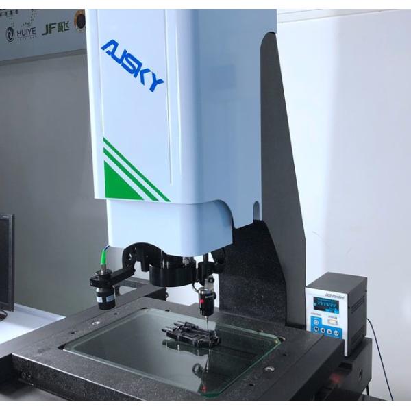
Large Scale 3d Measurement System Gantry Structure Optical Measuring Devices
Mechanism and Application Characteristics of Coordinate measuring machine:
1. Construction of the instrument:
Designed with workbench of a marble panel base and gantry mechanism, the instrument is characterized by steady accuracy, good adaptability to working environment, simple, strong, non-deformable and good-looking body structure, and ergonomically designed operating mechanism, and meanwhile is equipped with powerful measuring software and is easy to operate.
2. Movement of Mechanism:
this measuring instrument is provided with tri-axial automatic control and equipped with import precision Nidec patch grating system, Japan Panasonic servo high-efficiency motor system, Taiwan TBI screw rod, Taiwan HIWIN high-precision guide rail as well as professional measuring software for measurement.
3. Main functional configurations of instrument:
this instrument is used in with AUSKY professional automatic measurement software, Aotian special controller,MEAN WELL power supply, Panasonic servo motor drive system, TEO color 650TV CCD, PMS high resolution of 0.7–4.5 folds special high-definition Auto zoom and fixed-focus screen optical lens, LED partition program-controlled light source, import precision Nidec patch grating system, Lenovo computer,LCD monitor,keyboard, mouse, and the digital measurement.
4. Overall Merits:
A. Suitable for measuring applications of multi-variety, complex dimensions and demanding measuring accuracy, with even easy and quick measuring efficacy and enhanced measuring efficiency.
B. The instrument has the following merits with regard to image processing: automatic burrs skip-over, auto generating measurement reports and results statistics, and open for linking to printers, etc., suitable for wide industry applications.
Technical parameters
Paramter and Model | AMH1512 | |
Workbench | Glass table size(mm) | 1600X1248 |
Load-bearing weight(kg) | 30 | |
Travel | X axis(mm) | 1200 |
Y axis(mm) | 1500 | |
Z axis(mm) | 200 | |
Image and measurement system | Display resolution(mm) | 1/0.5(Optional) |
Instrument precision(um) | (4+L/200)um | |
Imaging system(CCD) | TEO HD color | |
Zoom objective(X) | Zoom objective 0.7~4.5X | |
Total video magnification(x) | 30~190X | |
Working distance(mm) | 96mm | |
Light source | LED programmable partiton light source(Coaxial light source optional) | |
Outline dimension(mm) | 2390X1830X1850 | |
Weight(kg) | 3500kg | |
Power supply | 220V AC 50Hz |
Configuration List:
Sequence number | Name | Unit | Quantity |
1 | Main body | PCS | 1 |
2 | Instrument table | PCS | 1 |
3 | AUSKY software | PCS | 1 |
4 | video card | PCS | 1 |
5 | Joystick | PCS | 1 |
6 | Dongle | PCS | 1 |
7 | Computer | PCS | 1 |
8 | Liquid crystal display | PCS | 1 |
9 | Aocheng optical calibration block | PCS | 1 |
10 | Precision probe(optional) | PCS | 1 |
11 | Keyboard and mouse | PCS | 1 |
12 | Specification warranty card certificate | PCS | 1 |
Introduction to the software functions:
Software interface
A. Multiple measuring methods, including auto edge-tracing, auto sectional edge-tracing, mouse on-screen point fetch, crossline pointing, proximity pointing, contrast and pinnacle pointing, contour pointing, probe pointing, laser pointing, and etc.
B. Powerful edge-tracing algorithm ensures sampling point accuracy and automatic pixel correction on sampling stability,
where, one stroke will enable automatic pixel correction, needless to shift frequently.
C. Element construction
Element structure technique, offers multiple methods, such as shifting, rotating, extracting, combining, paralleling,
plumbing, mirroring, symmetry, intersecting, tangentially structured elements; Element structure will enable user to
tackle some elements hard to measure, and consequently resulting in increased working efficiency; The compositional
process is to select elements for compositional involvement, select the result element, clear and simple. Options for
composition methods available in form of illustration.
D. Synchronization of laser and image
Before laser measuring, first to synchronize the laser and image, before following measuring can be performed. Using a
sample, find a cusp on the picture, before shift the crossline center to such cusp to call out the coordinate value, before
shift the laser spot to such cusp to call out the coordinate value of such cusp, click to confirm to wrap up the
synchronization, to achieve the image programming laser measuring.
(With this, in subsequent measuring process, whatever laser spot mining or imaging spot mining, they can be shifted to
the element center already mined)
E. Workpiece array macro
Responding to circumstances of placing simultaneously multiple identical or different fixtures on workbench, array on
each fixture can be identical or different. User can simply replace the fixture after measuring workpieces on one fixture,
which help save time and increase efficiency.
(Fixture 1) (Workpiece 1)
F. Import CAD graphics for measuring
The software supports measuring on workpieces with CAD graphics as template, which enable coordinate measuring or
comparison measuring. Such function is applicable to workpiece of any contour/shape within gauging range of the
measuring instrument.