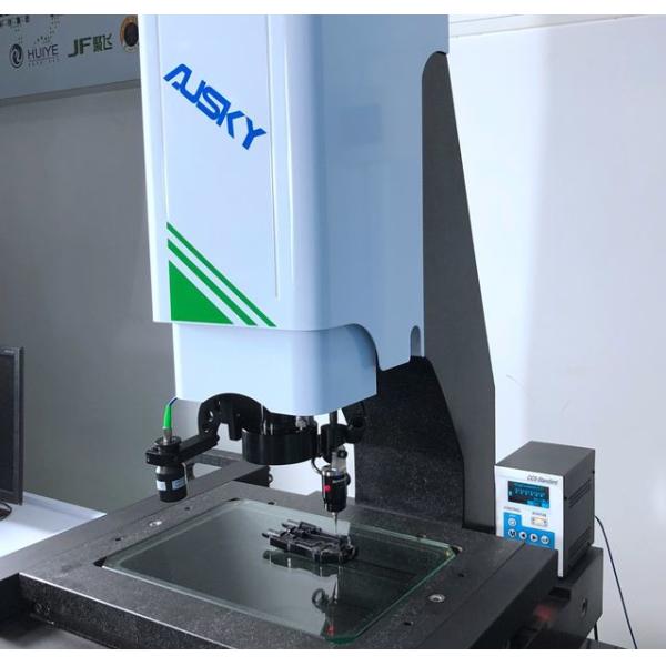
Full Automatic 3D Measuring Device Cantilever Type For Molds / Aircraft
Mechanism and Application Characteristics of Coordinate measuring machine:
1. Movement of Mechanism:
this measuring instrument is provided with tri-axial automatic control and equipped with Sinpo precision grating system, high-efficiency motor system, high-standard and high-precision V-type guide rail as well as professional measuring software for measurement.
2. Merits with the non-contact auto-measuring instrument:
This instrument can avoid human error of the “Object Work Piece” as caused by manual measuring, and can as well avoid secondary damage caused to “Object Work Piece” by manual measuring, with ensured mass stability and criteria consistency of the object work piece. This instrument can enhance multi-fold the detecting efficiency in the production process, identify the defects and control over non-yields beforehand in production process, and can meanwhile help lower part of the costs spent on manual detection, and increase the timeliness of product delivery.
3. Applicable scope:
this measuring instrument can be used for dimensional accuracy measurement of various molds, aircraft, automobile, mobile phone, computer, metals and hardware, plastics, electronics, die-cutting, screen printing and stencil, LCP film, PCB board, FPC, LCDTFT, glass cover-plate, TP, and frame of ultra-large LCD, as well as for auxiliary measurements such as 2D and 3D measuring as needed in reverse engineering, graphic R&D, design, plotting and editing, and laboratory, etc.
4. Overall Merits:
A. Suitable for measuring applications of multi-variety, complex dimensions and demanding measuring accuracy, with even easy and quick measuring efficacy and enhanced measuring efficiency.
B. The instrument has the following merits with regard to image processing: automatic burrs skip-over, auto generating measurement reports and results statistics, and open for linking to printers, etc., suitable for wide industry applications.
5. Saving cost:
This instrument can achieve multiple functions on the same set of equipment, resulting in saved user costs for repeated purchasing of measurement devices as well as saved labor costs and equipment occupation space. It can meet the needs of user enterprises for greater development in the future and the demand for rapid expansion of product testing to lay sound foundation for users’ quality assurance.
Technical parameters
Paramter and Model | AMQ540 | |
Workbench | Platfom size(mm) | 720X620 |
Glass table size(mm) | 550X450 | |
Load-bearing weight(kg) | 20 | |
Travel | X axis(mm) | 500 |
Y axis(mm) | 400 | |
Z axis(mm) | 200 | |
Image and measurement system | Display resolution(mm) | 1/0.5(Optional) |
Instrument precision(um) | (3+L/200)um | |
Imaging system(CCD) | HD color | |
Zoom objective(X) | Zoom objective 0.7~4.5X | |
Total video magnification(x) | 30~190X | |
Working distance(mm) | 96mm | |
Light source | LED programmable partiton light source(Coaxial light source optional) | |
Outline dimension(mm) | 1090X820X1700 | |
Weight(kg) | 550kg | |
Power supply | 220V AC 50Hz |
Configuration List:
Sequence number | Name | Unit | Quantity |
1 | Main body | PCS | 1 |
2 | Instrument table | PCS | 1 |
3 | AUSKY software | PCS | 1 |
4 | video card | PCS | 1 |
5 | Joystick | PCS | 1 |
6 | Dongle | PCS | 1 |
7 | Computer | PCS | 1 |
8 | Liquid crystal display | PCS | 1 |
9 | Aocheng optical calibration block | PCS | 1 |
10 | Precision probe(optional) | PCS | 1 |
11 | Keyboard and mouse | PCS | 1 |
12 | Specification warranty card certificate | PCS | 1 |
Introduction to the software functions:
E. Convenient program editing and modifying
Enable to modify conveniently light source data, kinetic data, focusing data, program location, measuring height, and
etc., as well as can replace existing elements with new elements.
F Ample tolerance functions
Multiple calculations of size and geometric tolerance available; Allowable for calculating 2D and 3D tolerance, e.g,
geometric tolerance as roundness, cylindricity, linearity, planeness, etc., as well as tolerances as location, parallelism,
verticality, tilt, concentricity, pulsation, etc.
G. Map navigation, scanning and contour tracking software provides powerful navigation functions
Can scan whole map by assigning a starting point and finishing point, and can also import the pictures taken by external
sensors for navigation; The scanning function can be used in reversing function, can designate starting point and
finishing point of the scanning, and special design algorithm; allow to increase scanning accuracy and practicality
through filtering impurities; allow to track open or closed graphics to have contour tracking, so as to obtain desired
contour. Can set number of scanning point, on contour, and software can automatically calculate scanning spacing.
H. Powerful tagging function
Available in multiple tagging types, for example, tagging of Distance, Angle, X Distance, Y Distance, Radius, Diameter,
Arc Length, and etc., allows to change position after tagging is finished, as well as to automatically tag user, that will
remain after program is over.
I. Probe measuring
Powerful functions of software probe measuring enable to character 2D & 3D elements such as height, plane, cylinder,
cone, sphere, ring, etc., and support multiple methods for establishing 3D coordinates system, with rapid and efficient
programming.
J. Composite measuring of probe and image
Composite measuring by complementing probe with image optical system achieves multi-purpose measuring of image
and probe.
K. Workpiece array and array macro function
Such function is applied in automatic image measuring instrument. When a bunch of identical workpieces are placed and
literally equally spaced on one measure fixture, measure one of the workpieces at first, before measure all the
workpieces on the measure fixture. This will not only save the time for edge-tracing measuring, but also simplify the
user program.
L. Laser measuring
Laser measuring sees an increasing popularity in imaging device measuring. Our software is also improved and
optimized responding to the measuring call. We herein introduce as below:
M. Connection and interfacing with laser
Currently, our measuring device can connect with laser of following brands: Keyence, Panasonic, Omron, Miyi, Stil,
ERT, Sunny, and etc. Select the laser and COM you wish to connect with in the Laser List in the Parameter Setting.
(After connection, the measuring method using laser measuring is indicated as below(L: Reading of the line is the
current laser reading, and corresponding interface of laser measuring will also pop up in the Graphic Zone)
N. Import CAD graphics for measuring
The software supports measuring on workpieces with CAD graphics as template, which enable coordinate measuring or
comparison measuring. Such function is applicable to workpiece of any contour/shape within gauging range of the
measuring instrument.