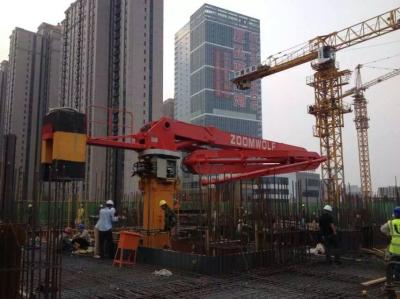
Concrete Placing Boom Simple Floor Climbing Frame Structure
Structural characteristic of ZOOMWOLF concrete placing boom
1, Internal hydraulic oil tank, compact structure, easy installation.
2, The square column is formed by bending and piecing welding of low-alloy steel plate, with beautiful appearance, good strength and rigidity.
3, Floor climbing frame structure is simple, easy to disassemble and install.
4, Under the premise of meeting the requirements of strength and stiffness, the optimized design of the boom pursues light quality.
Features
Optimal design of boom-&column-structure ,Inner hydraulic oil tank renders a compact placement.
The key components of hydraulic- and electrical-system are from world famous brand,which ensure safety and stability.
For option:
1. Standard types without counter weight
2. Floor or shaft climbing
3. Step speed or stepless speed(proportional control)
4. Column length:5m,8m,10m
5. Delivery pipes for option as project budget:
⑴ Ordinary single straight pipe and cast steel bend,service life not more than 20,000m3 ;
⑵ High wear resistance double straight pipe and bend,service life not less than 50,000m3;
Technical Specifications | ||||||
Model of placing boom | HGY29S-3R | HGY29P-3R | HGY29SC-3R | HGY29PC-3R | ||
Performance | Max. radius (m) | 29 | ||||
Free standing height, | 22.7m,400° | |||||
Slewing range | ||||||
Working temperature(℃) | 0~60℃ | |||||
Counter weight(kg) | / | 2930 | ||||
Total weight(kg) | 19100 | 22030 | ||||
Supply power to equipment | 380V/50Hz | |||||
Electric motor | Motor model | Y2-160L-4 | ||||
Power(kW) | 15 | |||||
Hydraulic system | System pressure(MPa) | 32 | ||||
Flow(L/min) | 18 | |||||
Oil tank capacity(L) | 280 | |||||
Control mode | (Cable+Radio) remote control | |||||
Clearing mode for concrete pipe | Water clear / Dry clear | |||||
Section of tubular column (m×m) | 0.75×0.75 | |||||
Arm(Booms) | Boom model | fully hydraulic foldable arms | ||||
Delivery pipeline diameter | DN125mm | |||||
Length of end hose (〃×m) | 5〃×3 | |||||
The first section | Length(m) | 10.9 | ||||
Articulation | -2.5°~82.5° | |||||
The second section | Length(m) | 9.6 | ||||
Articulation | 0°~180° | |||||
The third section | Length(m) | 8.5 | ||||
Articulation | 0°~180° | |||||
Climbing | Climbing mode | Cylinder jack lifting | ||||
Internal climbing step distance(m) | 0.52 | |||||
Floor Frame | Hole prepared in floor | |||||
Shaft Frame | Size of climbing shaft : 2.0m-2.7m | |||||
Min. space between internal climbing frame | Climbing(m) | 3 | ||||
Placing concrete(m) | 6 | |||||
Rest(m) | 6 |
About the model
HGY ×× S or P C or blank - × R
① ② ③ ④ ⑤
① Hydraulic concrete distributor
② Round number of Max.radius(m)
③ Step speed regulation(S)or
Proportional control speed regulation(P)
④ With(C)or without(blank) counter weight
⑤ Arm section number ×Roll folding(R)
【Identification letter description】
S: Step-speed adjustment
P: Proportional (Stepless speed regulation)
C: Counter weight
【The sample】
1. Model HGY33S-3R means:
Without counter weight,max.radius 33m,step speed regulation and 3 roll-folding arms.
2. Model HGY33PC-4R means:
With counter weight,max.radius 33m, proportional control speed regulation and 4 roll-folding arms.