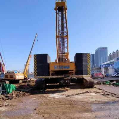
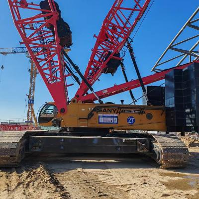
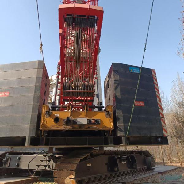
Crawler crane models: XGC55
Maximum rated lifting capacity: 55t/3.7m
Maximum rated lifting moment: 203.5t.m
Product component and system description
The upper part
Boom combination
The boom of the XGC55 crawler crane is made of high-strength seamless steel pipes as chord and belly tubes, supplemented by high-strength steel plates welded in sections to form a four-chord space truss structure with equal cross-sections in the middle and variable cross-sections at both ends. With the help of precise finite element analysis and calculation, the potential of the boom is fully utilized and the lifting capacity is greatly improved.
The maximum lifting capacity of the main boom is 55t/3.7m, the maximum lifting moment is 203.5t.m, and the main boom frame can be selected in lengths of HB13~HB52. The main boom consists of: bottom boom 1×6.5m, top boom 1×6.5m, middle boom 1×3m, middle boom 3×6m, middle boom 2×9m.
The maximum lifting capacity of the fixed jib is 11.4t (2 times), the maximum lifting moment is 10.7t×12m=128.4t.m, the main arm length of the fixed jib is HB25~HB43, and the jib configuration length of the fixed jib is HF7~HF16. The fixed jib consists of: bottom section arm 1×4m, top section arm 1×3m, middle section 1×3m, middle section 1×6m, bracket 1×3m.
The maximum lifting capacity of the main arm with a single pulley at the arm end is 6t (1 times), the length of the single pulley at the arm end is 1.1m, and the main arm length that can be used for the single pulley at the arm end is HB13~HB49.
Boom luffing member
The luffing is mainly done by cables, supplemented by plates. The cables are made of mature process structures, which are safe and reliable; the plates are made of high-strength steel plates cut and formed in one go, without welding, with few manufacturing defects and high safety factor.
Turntable
The turntable is the key bearing structure for connecting the upper and lower vehicles. The main load-bearing structure adopts a flat box structure welded from high-strength steel plates. The cantilever structures on both sides are welded to increase the space of the whole machine for arranging fixed loads. The turntable is connected to the lower vehicle through a slewing bearing. The main arm bottom section, herringbone frame, lifting mechanism, luffing mechanism and counterweight are arranged on the main load-bearing structure; the control room, engine system, main pump, hydraulic valve, electric control cabinet and other structures are arranged on the cantilever structures on both sides. The main structure of the turntable and the cantilever structures on both sides are designed according to the load-bearing conditions of the whole machine, with reasonable structure and good overall strength and rigidity.
The herringbone frame
The herringbone frame is composed of a double-limb structure with a reinforced crossbeam between the two limbs, which has good stability. The main structure of the herringbone frame is a high-quality seamless steel pipe, which effectively reduces the amount of welding, has few manufacturing defects, and has a high safety factor. The herringbone frame has two states, high and low, which can be raised during operation and laid down during transportation. The herringbone frame is equipped with self-lifting rollers, which can realize the self-lifting function with the cooperation of the bottom section of the main arm.
Machine structure
The structure and purpose of this machine are as follows:
No. |
Mechanism name |
Usage |
Layout location |
1 |
Main lifting mechanism |
Main boom operation |
Center-front direction of the turntable |
2 |
Auxiliary lifting mechanism |
Fixed jib, single pulley lifting operation at the arm end |
Turntable middle |
3 |
Luffing mechanism |
Main boom luffing |
Behind the turntable |
4 |
Slewing mechanism |
Crane slewing |
Front of turntable |
5 |
Traveling mechanism |
Machine traveling |
Crawler drive wheel |
Lifting mechanism
The lifting mechanism includes the main lifting mechanism and the auxiliary lifting mechanism.
The main lifting and auxiliary lifting mechanisms are driven by a planetary gear reducer driven by a quantitative motor. The main hook or auxiliary hook is lifted and lowered through the drum and pulley set. The lifting and lowering speed of the main lifting and auxiliary lifting mechanisms is increased through the double pump oil supply function.
The main lifting and auxiliary lifting mechanisms are built-in planetary reducers, and a negative brake design multi-plate wet laminated normally closed brake is adopted to realize the "spring brake/hydraulic release" function, which is safe and reliable. It is lubricated by splashing oil and does not require maintenance. The lifting mechanism also has the characteristics of convenient oil change, low noise, high efficiency, and long life. At the same time, it has excellent micro-speed performance.
The lifting drum is made of ductile iron with good vibration absorption, and the double-folded rope groove ensures that the wire rope is wound in multiple layers without tangling, which effectively extends the service life of the wire rope.
The main hoisting mechanism uses a left-handed same-direction twisted anti-rotation special steel wire rope with independent steel core, high breaking tension and high extrusion resistance, with a rated single rope tension of 6t, a wire rope diameter of φ 20 mm and a length of 200m.
The auxiliary hoisting mechanism also uses an independent steel core, high breaking tension and high extrusion resistance anti-rotation special steel wire rope with a rated single rope tension of 6t, a wire rope diameter of φ 20 mm and a length of 130m.