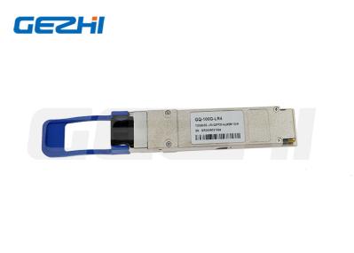
40G QSFP+ LR4 1310nm 10km SMF Fiber Transceiver Module
Description
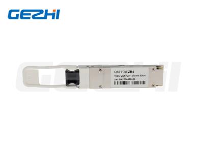
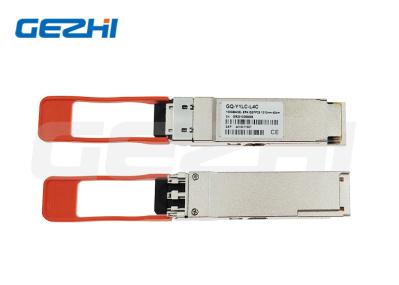
This product is a transceiver module designed for 2m-10km optical communication applications. The design is compliant to 40GBASE-LR4 of the IEEE P802.3ba standard. The module converts 4 inputs channels (ch) of 10Gb/s electrical data to 4 CWDM optical signals, and multiplexes them into a single channel for 40Gb/s optical transmission. Reversely, on the receiver side, the module optically de-multiplexes a 40Gb/s input into 4 CWDM channels signals, and converts them to 4 channel output electrical data.
The central wavelengths of the 4 CWDM channels are 1271, 1291, 1311 and 1331 nm as members of the CWDM wavelength grid defined in ITU-T G694.2. It contains a duplex LC connector for the optical interface and a 148-pin connector for the electrical interface. To minimize the optical dispersion in the long-haul system, single-mode fiber (SMF) has to be applied in this module.
The product is designed with form factor, optical/electrical connection and digital diagnostic int
Features
4 channels full-duplex transceiver module
Up to 11.2Gbps data links per channel
Maximum link length of 10Km
4 CWDM lanes MUX/DEMUX design
Built-in digital diagnostic functions
Hot-pluggable QSFP+ form factor
Single 3. 3V power supply
Operating temperature: 0℃ to 70℃
RoHS 6 compliant(lead free)
Digital Diagnostic Monitor(DDM)
Power Consumption < 2W
Application
Switch, router and HBAs
4CH SDR, DDR and QDR
Client-side 40G Telecom Connections
Transmitter Optical Characteristics
Parameter | Symbol | Min. | Typical | Max | Unit | Notes | |||||||
Wavelength Assignment | L0 | 1264.5 | 1271 | 1277.5 | nm | ||||||||
L1 | 1284.5 | 1291 | 1297.5 | nm | |||||||||
L2 | 1304.5 | 1311 | 1317.5 | nm | |||||||||
L3 | 1324.5 | 1331 | 1337.5 | nm | |||||||||
Transmitter | |||||||||||||
Side-mode Suppression Ratio | SMSR | 30 | - | - | dB | ||||||||
Total Average Launch Power | PT | - | - | 8.3 | dBm | ||||||||
Average Launch Power, each Lane | -7 | - | 2.3 | dBm | |||||||||
Optical Modulation Amplitude, each Lane | OMA | -4 | - | +3.5 | dBm | ||||||||
Difference in Launch Power between any two Lanes (OMA) | - | - | 6.5 | dB | |||||||||
Launch Power in OMA minus Transmitter and Dispersion Penalty (TDP), each Lane | -4.8 | - | dBm | ||||||||||
TDP, each Lane | TDP | 2.3 | dB | ||||||||||
Extinction Ratio | ER | 3.5 | - | - | dB | ||||||||
Relative Intensity Noise | Rin | - | - | -128 | dB/Hz | 12dB reflection | |||||||
Optical Return Loss Tolerance | - | - | 20 | dB | |||||||||
Transmitter Reflectance | RT | -12 | dB | ||||||||||
Transmitter Eye Mask Definition {X1, X2, X3, Y1, Y2, Y3} | {0.25,0.4,0.45,0.25,0.28,0.4} | ||||||||||||
Average Launch Power OFF Transmitter, each Lane | Poff | -30 | dBm | ||||||||||
Receiver | |||||||||||||
Damage Threshold | THd | 3.3 | dBm | 1 | |||||||||
Average Power at Receiver Input, each Lane | -13.7 | 2.3 | dBm | ||||||||||
Receiver Reflectance | RR | - | - | -26 | dB | ||||||||
Receiver Power (OMA), each Lane | - | - | 3.5 | dBm | |||||||||
Stressed Receiver Sensitivity in OMA, each Lane | - | - | -9.9 | dBm | |||||||||
Receiver Sensitivity, each Lane | SR | - | - | -11.5 | dBm | ||||||||
Difference in Receive Power between any two Lanes (OMA) | 7.5 | dB | |||||||||||
Receive Electrical 3 dB upper Cutoff Frequency, each Lane | 12.3 | GHz | |||||||||||
Conditions of Stress Receiver Sensitivity Test2 | |||||||||||||
Vertical Eye Closure Penalty, each Lane | 1.6 | dB |
|
||||||||||
Stressed Eye Jitter, each Lane | 0.3 | UI |