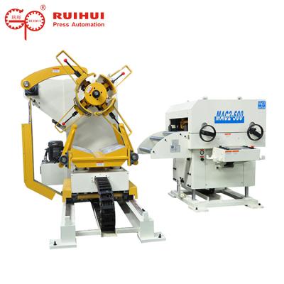
Unwinding Decoiler And Straightener Equipment Metal Slab Stamping Material Rack
As the most used unwinding equipment in the stamping industry - heavy-duty material frame, the traditional use of contact mechanical friction to brake, the actual discharge, unwinding, the friction plate is easy to damage, low life, poor braking effect, and can not Know exactly the amount of braking force.
This traditional braking method, when the material load capacity is large, the stability and safety are particularly poor, and a stable and reliable braking method is needed at this time.
Therefore, Ruihui Machinery has adopted the hydraulic valve brake method to replace the traditional butterfly brake method in the production of hydraulic heavy-duty material frame. The hydraulic pressure heavy-duty material frame hydraulic brake valve body contains three sets of check valves and one overflow. Flow valve, reasonable design.
When the material frame is running, it is only necessary to adjust the pressure of the relief valve to adjust the braking force. It has stable structure, reliable, no noise, adjustable brake pressure, simple and stable adjustment, long service life and remarkable braking effect. The dynamic pressure is readable, and it can ensure the high-efficiency unwinding of the oil pressure heavy material frame, and it can brake for a long time, ensuring the positive and negative braking force phase and so on.
The working principle is as follows: when the electromagnet IDT on the heavy material rack reversing valve is de-energized, and the electromagnet DT on the reversing valve is energized, the oil flows through the inlet valve through the inlet port and the outlet port joint. The hydraulic motor of the heavy material frame is driven to rotate forward or reverse, and the rotating shaft is actively unwinded. At this time, the system pressure is set by the relief valve.
Specification:
Model | MAC2-400 | MAC2-500 | MAC2-600 | MAC2-800 | ||
Stock Width(mm) | 50-400 | 50-500 | 50-600 | 50-800 | ||
Stock Thickness(mm) | 0.3~3.2 | 0.3-3.2 | 0.3-3.2 | -3.2 | ||
Max.Coil Weight(kg) | 3000 | 3000 | 3000 | 5000 | 5000 | 7000 |
Max.Coil O.D.(mm) | 1200 | 1200 | 1200 | |||
Coil I.D.(mm) | 8 | 8 | 508 | 508 | ||
Feed Length(mm) | ~500* | ~500* | ~500* | ~500* | ||
Max. Line Speed(m/min) | 16-24 | 16-24 | 16-24 | 16-24 | ||
Work Roll Number(pieces) | upper 6 lower 5 | upper 6 lower 5 | upper 6 lower 5 | upper 6 lower 5 | ||
Feed Roll Number(set) | 1 | 1 | 1 | 1 | ||
Main Motor(kw) | AC2.9 | AC2.9 | AC4.4 | AC4.4 | ||
Mandrel Expansion | hydraulic | hydraulic | hydraulic | hydraulic | ||
Reel Motor(kw) | 1.5 | 1.5 | 1.5 | 2.2 | 2.2 | 3.7 |
Power(V) | 3 Phase 220V/380V/50HZ | |||||
Operating Air(Mpa) | 0.49 | 0.49 | 0.49 | 0.49 |
Straigtening performance:
tock Thicknees (mm) | Stock Width (mm) | |||
0.3 | 400 | 500 | 600 | 800 |
0.4 | ||||
0.6 | ||||
0.8 | ||||
1.0 | ||||
1.2 | ||||
1.4 | ||||
1.6 | 470 | 470 | ||
1.8 | 400 | 400 | ||
2.0 | 360 | 360 | ||
2.3 | 300 | 300 | 300 | 300 |
2.5 | 230 | 230 | 230 | 230 |
2.8 | 150 | 150 | 150 | 150 |
3.2 | 110 | 110 | 110 | 110 |
*1:(Pneumatic):Option in case of pneumatic mandrel expansion is provi