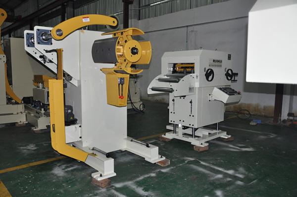
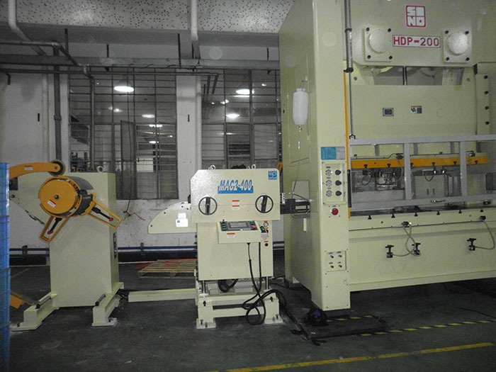
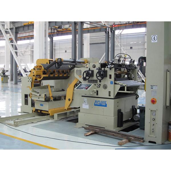
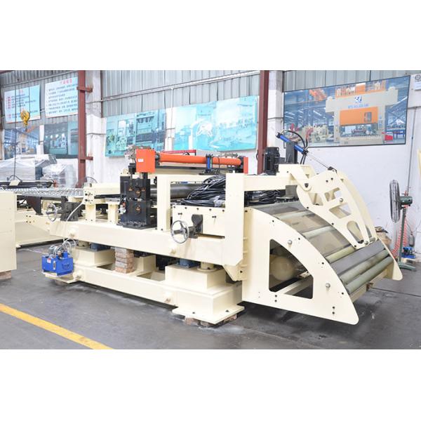
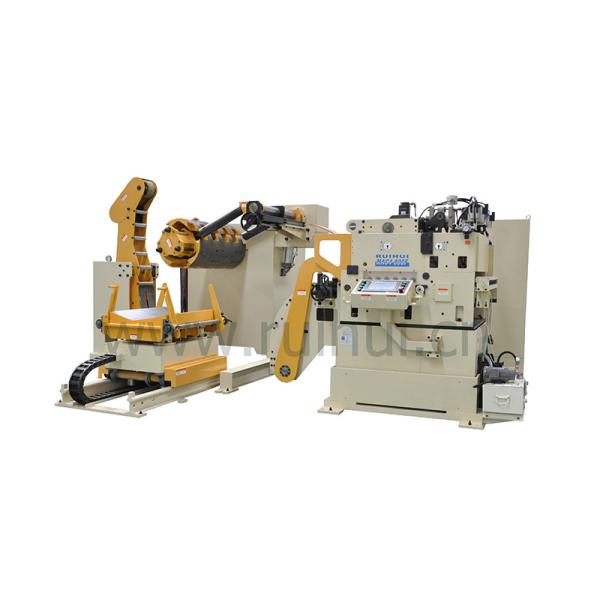
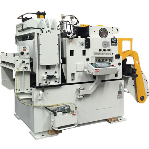
Clip Feeder, CNC Roller Feeder, Servo Feeder, High speed mechanical gear feeder (MAC3-600)
The clip feeder consists of six parts: the fuselage, the input mechanism, the transmission adjustment mechanism, the feeding mechanism and the timing mechanism.
The clip-on feeder body assembly components are fixed on the base horizontal plate, and the vertical plate of the base plate is provided with a plurality of long holes, and the height of the clamp can be adjusted to the seat plate on the feed side of the punching machine.
A front tray is arranged on the front end of the fuselage, and a rear tray is connected to the rear end surface. The number of open guide grooves is arranged on the rear tray surface to adjust the fixed and smooth positioning plates of the same number of extension brackets.
The input shaft of the input mechanism extends out of the fuselage to connect the force gauge pulley, and the timing pulley connects the punch crank through the timing belt to provide rotary power for the clip feeder main shaft.
The feeding turntable of the feeding mechanism of the clip feeder feeds a T-shaped groove on the center line, and a T-shaped block is screwed into a screw to connect the driving shaft of the force mechanism to transmit the rotating power.
The screw is provided with a digital disc sleeve disposed outside the sealing wall of the T-shaped groove, and the screw sleeve located in the T-shaped groove is sleeved with a thrust bearing to lock a nut, so that the clamping screw and the digital disk are pivoted In the sealing wall of the T-shaped groove, and the screw is arranged with a gap block adjacent to the T-shaped block, a recessed hole is arranged in each of the adjacent faces to press a backlash spring.
The T-block is connected to a shaft pivoting and connecting a link group to a feeding frame which is arranged on the top of the heavy body of the fuselage to operate the feeding action of the material at a predetermined feeding timing.
Products:
Specification:
Model | MAC2-400 | MAC2-500 | MAC2-600 | MAC2-800 | ||
Stock Width(mm) | 50-400 | 50-500 | 50-600 | 50-800 | ||
Stock Thickness(mm) | 0.3~3.2 | 0.3-3.2 | 0.3-3.2 | -3.2 | ||
Max.Coil Weight(kg) | 3000 | 3000 | 3000 | 5000 | 5000 | 7000 |
Max.Coil O.D.(mm) | 1200 | 1200 | 1200 | |||
Coil I.D.(mm) | 8 | 8 | 508 | 508 | ||
Feed Length(mm) | ~500* | ~500* | ~500* | ~500* | ||
Max. Line Speed(m/min) | 16-24 | 16-24 | 16-24 | 16-24 | ||
Work Roll Number(pieces) | upper 6 lower 5 | upper 6 lower 5 | upper 6 lower 5 | upper 6 lower 5 | ||
Feed Roll Number(set) | 1 | 1 | 1 | 1 | ||
Main Motor(kw) | AC2.9 | AC2.9 | AC4.4 | AC4.4 | ||
Mandrel Expansion | hydraulic | hydraulic | hydraulic | hydraulic | ||
Reel Motor(kw) | 1.5 | 1.5 | 1.5 | 2.2 | 2.2 | 3.7 |
Power(V) | 3 Phase 220V/380V/50HZ | |||||
Operating Air(Mpa) | 0.49 | 0.49 | 0.49 | 0.49 |
Straigtening performance:
tock Thicknees (mm) | Stock Width (mm) | |||
0.3 | 400 | 500 | 600 | 800 |
0.4 | ||||
0.6 | ||||
0.8 | ||||
1.0 | ||||
1.2 | ||||
1.4 | ||||
1.6 | 470 | 470 | ||
1.8 | 400 | 400 | ||
2.0 | 360 | 360 | ||
2.3 | 300 | 300 | 300 | 300 |
2.5 | 230 | 230 | 230 | 230 |
2.8 | 150 | 150 | 150 | 150 |
3.2 | 110 | 110 | 110 | 110 |
*1:(Pneumatic):Option in case of pneumatic mandrel expansion is provi