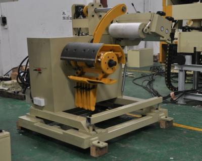
Servo feeder adjustment test case
1. Start the correcting machine or material frame and slowly release the material.
2. Adjust the position of the two stopper wheels according to the width of the material, so as not to hinder the operation of the material.
3. will relax the handle on the stage, put the material between the upper and lower rollers, put down the loose handle, loosen the fixing screw of the material thickness adjustment handle, adjust the handle up and down, let the relaxation bracket have a swing gap of about 5mm, and then lock the handle fixing screw .
4. The function of the pressure spring is to apply pressure to the upper roller, so that the upper roller can press the material and send the material out, so the pressure should be based on the principle that the material does not slip, and the pressure should be increased when the thickness is thick.
5. After setting the length of the feeder, look at the actual situation and set the speed of the feeder accordingly. The method of setting will be described in detail later.
6. After the relevant parameters of the feeder are set, the actual feeder length is not the same as the set value due to the number of the divisor. Therefore, in the manual mode, press the feeder test, punch, stroke, stamping, Adjust the actual length of the feeder.
7. When the tip of the guide pin in the mold enters the guide pin hole, adjust the loose screw to the bearing that touches the loose bracket until the material is relaxed, and the screw nut is locked (the pneumatically loose feeder machine should be adjusted) The angle of relaxation is about ±15o in the next death.)
8. The adjustment of the feeding machine is adjusted by the rotating cam of the punching machine. The so-called feeder starting signal is to start the feeding machine at which angle of the punching crankshaft. The recommended angle of the feeding machine is 9 to 3 (240o). -90o).
9. After the setting is completed, the test mode should be single-punched first, and the production can be continued after adjustment.
Specification:
Model | MAC2-400 | MAC2-500 | MAC2-600 | MAC2-800 | ||
Stock Width(mm) | 50-400 | 50-500 | 50-600 | 50-800 | ||
Stock Thickness(mm) | 0.3~3.2 | 0.3-3.2 | 0.3-3.2 | -3.2 | ||
Max.Coil Weight(kg) | 3000 | 3000 | 3000 | 5000 | 5000 | 7000 |
Max.Coil O.D.(mm) | 1200 | 1200 | 1200 | |||
Coil I.D.(mm) | 8 | 8 | 508 | 508 | ||
Feed Length(mm) | ~500* | ~500* | ~500* | ~500* | ||
Max. Line Speed(m/min) | 16-24 | 16-24 | 16-24 | 16-24 | ||
Work Roll Number(pieces) | upper 6 lower 5 | upper 6 lower 5 | upper 6 lower 5 | upper 6 lower 5 | ||
Feed Roll Number(set) | 1 | 1 | 1 | 1 | ||
Main Motor(kw) | AC2.9 | AC2.9 | AC4.4 | AC4.4 | ||
Mandrel Expansion | hydraulic | hydraulic | hydraulic | hydraulic | ||
Reel Motor(kw) | 1.5 | 1.5 | 1.5 | 2.2 | 2.2 | 3.7 |
Power(V) | 3 Phase 220V/380V/50HZ | |||||
Operating Air(Mpa) | 0.49 | 0.49 | 0.49 | 0.49 |
Straigtening performance:
tock Thicknees (mm) | Stock Width (mm) | |||
0.3 | 400 | 500 | 600 | 800 |
0.4 | ||||
0.6 | ||||
0.8 | ||||
1.0 | ||||
1.2 | ||||
1.4 | ||||
1.6 | 470 | 470 | ||
1.8 | 400 | 400 | ||
2.0 | 360 | 360 | ||
2.3 | 300 | 300 | 300 | 300 |
2.5 | 230 | 230 | 230 | 230 |
2.8 | 150 | 150 | 150 | 150 |
3.2 | 110 | 110 | 110 | 110 |
*1:(Pneumatic):Option in case of pneumatic mandrel expansion is provi