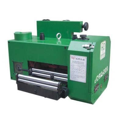
The die gap refers to the sum of the gaps on both sides of the punch into the lower die. It is related to the plate thickness, material and stamping process. Choosing a suitable die gap can ensure good punching quality, reduce burrs and collapse, and maintain the plate. The material is flat, effectively preventing the material from being taken and prolonging the life of the mold.
By checking the condition of the stamping waste, the CNC feeder can determine whether the mold gap is appropriate. If the gap is too large, the scrap will have a rough undulating fracture surface and a small shiny surface. The larger the gap, the larger the angle formed between the fracture surface and the shiny surface, the curling and fracture will occur during punching, and even a thin edge protrusion will appear. Conversely, if the gap is too small, the scrap will have a small angle of fracture and a large shiny surface.
When performing local punching such as grooving, nibbling, shearing, etc., the lateral force will deflect the punch and cause the unilateral clearance to be too small, and sometimes the edge offset may excessively scratch the lower die, causing rapid wear of the upper and lower dies. When the mold is punched with the best clearance, the fracture surface and the shiny surface of the scrap have the same angle and overlap each other, so that the punching force is minimized and the punching burr is small.
If the workpiece has excessive burrs or unusual noise during stamping, the mold may be passivated. The CNC feeder checks the punch and the lower die. When the edge is worn to produce an arc with a radius of about 0.10 mm, it is sharpened. Practice has shown that frequent micro-sharpening, rather than waiting for non-grinding, can not only maintain good workpiece quality, reduce punching force, but also prolong the life of the mold by more than one time.
Specification:
Model | MAC2-400 | MAC2-500 | MAC2-600 | MAC2-800 | ||
Stock Width(mm) | 50-400 | 50-500 | 50-600 | 50-800 | ||
Stock Thickness(mm) | 0.3~3.2 | 0.3-3.2 | 0.3-3.2 | -3.2 | ||
Max.Coil Weight(kg) | 3000 | 3000 | 3000 | 5000 | 5000 | 7000 |
Max.Coil O.D.(mm) | 1200 | 1200 | 1200 | |||
Coil I.D.(mm) | 8 | 8 | 508 | 508 | ||
Feed Length(mm) | ~500* | ~500* | ~500* | ~500* | ||
Max. Line Speed(m/min) | 16-24 | 16-24 | 16-24 | 16-24 | ||
Work Roll Number(pieces) | upper 6 lower 5 | upper 6 lower 5 | upper 6 lower 5 | upper 6 lower 5 | ||
Feed Roll Number(set) | 1 | 1 | 1 | 1 | ||
Main Motor(kw) | AC2.9 | AC2.9 | AC4.4 | AC4.4 | ||
Mandrel Expansion | hydraulic | hydraulic | hydraulic | hydraulic | ||
Reel Motor(kw) | 1.5 | 1.5 | 1.5 | 2.2 | 2.2 | 3.7 |
Power(V) | 3 Phase 220V/380V/50HZ | |||||
Operating Air(Mpa) | 0.49 | 0.49 | 0.49 | 0.49 |
Straigtening performance:
tock Thicknees (mm) | Stock Width (mm) | |||
0.3 | 400 | 500 | 600 | 800 |
0.4 | ||||
0.6 | ||||
0.8 | ||||
1.0 | ||||
1.2 | ||||
1.4 | ||||
1.6 | 470 | 470 | ||
1.8 | 400 | 400 | ||
2.0 | 360 | 360 | ||
2.3 | 300 | 300 | 300 | 300 |
2.5 | 230 | 230 | 230 | 230 |
2.8 | 150 | 150 | 150 | 150 |
3.2 | 110 | 110 | 110 | 110 |
*1:(Pneumatic):Option in case of pneumatic mandrel expansion is provi