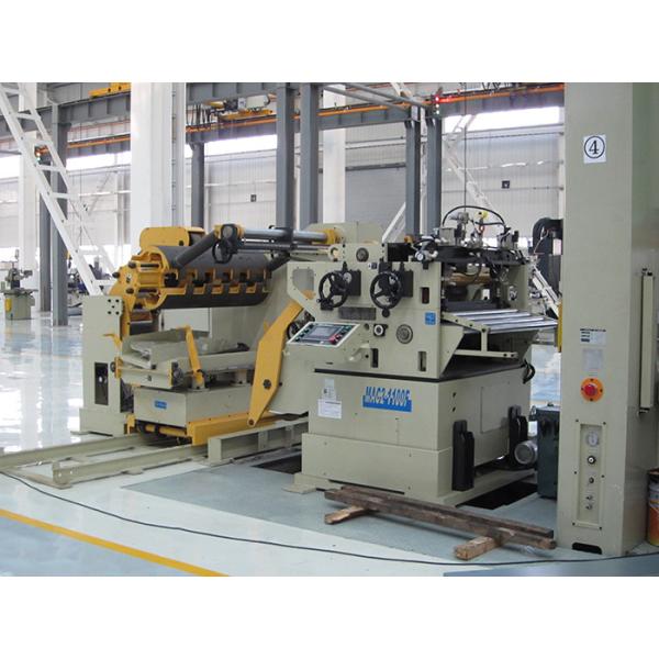
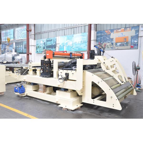
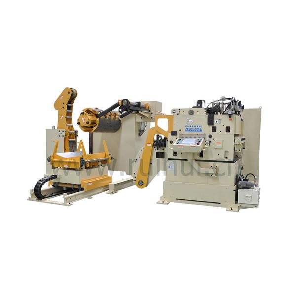
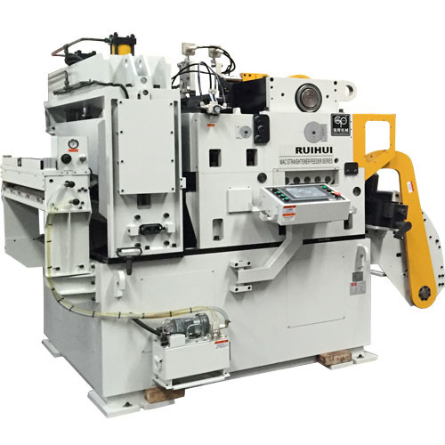
The pneumatic feeder is the most affordable feeder in the stamping industry, as it automates stamping production with minimal customer investment.
1. Install the three-point combination before the air inlet of the pneumatic feeder, and add a proper amount of lubricating oil to the three-point combination oiler, then connect the air source and adjust the screw on the three-point combination filter to adjust the intake air. The pressure is such that the air pressure of the pneumatic feeder is maintained at 4.5 kg/cm2 to 5 kg/cm2.
2. Open the air valve of the pneumatic feeder and let the airflow enter the pneumatic feeder. At this time, check whether there are air leakage in each part of the pneumatic feeder. If there is any air leakage, re-apply the waterproof tape and tighten until there is no leakage. So far.
3. When the airflow enters the pneumatic feeder, the floating rod will bounce up, and then press the floating rod down by hand, which will make the moving splint of the pneumatic feeder slide, and check whether the sliding is stable in time. At the same time, observe whether the action of the fixed splint and the moving splint are synchronized. When the fixed splint is required to be clamped, the moving splint should be in a relaxed state.
4. Press the pneumatic feeder floating rod repeatedly. If the moving slider hits the recoil pad, the speed of the feeder is very fast. The feeding speed should be adjusted properly. At this time, the speed of the machine can be adjusted by using the speed adjusting screw. It is enough to make the running speed and the punching speed consistent.
5. Finally, the air valve of the pneumatic feeder is closed, the material to be fed is moved from the inlet to the moving splint and the fixed splint, and then the gas source is turned on, and the punch is started to check whether there is a bias in the feeding process. Whether the speed can fully match the punch.
Specification:
Model | MAC2-400 | MAC2-500 | MAC2-600 | MAC2-800 | ||
Stock Width(mm) | 50-400 | 50-500 | 50-600 | 50-800 | ||
Stock Thickness(mm) | 0.3~3.2 | 0.3-3.2 | 0.3-3.2 | -3.2 | ||
Max.Coil Weight(kg) | 3000 | 3000 | 3000 | 5000 | 5000 | 7000 |
Max.Coil O.D.(mm) | 1200 | 1200 | 1200 | |||
Coil I.D.(mm) | 8 | 8 | 508 | 508 | ||
Feed Length(mm) | ~500* | ~500* | ~500* | ~500* | ||
Max. Line Speed(m/min) | 16-24 | 16-24 | 16-24 | 16-24 | ||
Work Roll Number(pieces) | upper 6 lower 5 | upper 6 lower 5 | upper 6 lower 5 | upper 6 lower 5 | ||
Feed Roll Number(set) | 1 | 1 | 1 | 1 | ||
Main Motor(kw) | AC2.9 | AC2.9 | AC4.4 | AC4.4 | ||
Mandrel Expansion | hydraulic | hydraulic | hydraulic | hydraulic | ||
Reel Motor(kw) | 1.5 | 1.5 | 1.5 | 2.2 | 2.2 | 3.7 |
Power(V) | 3 Phase 220V/380V/50HZ | |||||
Operating Air(Mpa) | 0.49 | 0.49 | 0.49 | 0.49 |
Straigtening performance:
tock Thicknees (mm) | Stock Width (mm) | |||
0.3 | 400 | 500 | 600 | 800 |
0.4 | ||||
0.6 | ||||
0.8 | ||||
1.0 | ||||
1.2 | ||||
1.4 | ||||
1.6 | 470 | 470 | ||
1.8 | 400 | 400 | ||
2.0 | 360 | 360 | ||
2.3 | 300 | 300 | 300 | 300 |
2.5 | 230 | 230 | 230 | 230 |
2.8 | 150 | 150 | 150 | 150 |
3.2 | 110 | 110 | 110 | 110 |
*1:(Pneumatic):Option in case of pneumatic mandrel expansion is provi