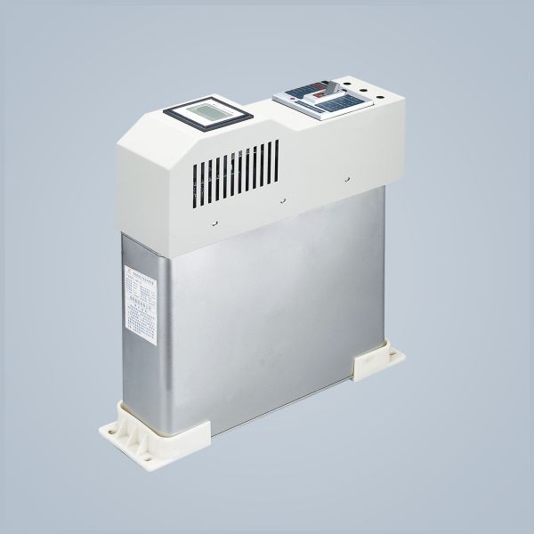
Any Combination Of Low - Voltage Bus Pull - Out Distribution Control Switch Cabinet
Use:
The low-voltage switchboard switch cabinet consists of power distribution center (PC) cabinet and motor control center (MCC). It is suitable for power users of power plants, substations and industrial and mining enterprises as AC 50Hz, with working voltage to 660V and working current to 3150A, as the power distribution control of power distribution, motor control and lighting.
Main Technical Parameters:
Rated voltage frequency (H) | 50 | |
Rated operating voltage (V) | 380.660 | |
Rated Insulation Voltage (V) | 660 | |
Rated operating current (A) | horizontal bus | 630-31 50 |
vertical bus | 600 | |
Rated short-time tolerance current | horizontal bus | 80kA(Effective value)/1s |
vertical bus | 50kA( effective value )/1s | |
Rated peak tolerance current | Horizontal myodia | 176kA/0.1S |
vertical bus | 110KA/0.1S | |
Main Circuit connector (A) | 200.400 | |
Auxiliary circuit connector (A) | 10 | |
Working frequency pressure resistance for 1 minute(V) | 2500 | |
IP Grade | IP40 | |
operation mode | on the spot. Far away, automatic |
Characteristic:
This series of products have high separation ability, good thermal stability, advanced and reasonable structure, practical electrical scheme, series.Strong versatility, any combination of various scheme units, a cabinet contains more circuits, saving area area, beautiful appearance, high protection level, safety and reliable, convenient maintenance and other advantages.
This product meets the IEC 349 NEMA CIS-2322 standard, the national standard of GB 2751.2005 Low-voltage Complete Switchgear and the ZBK 63001 professional standard of Low-voltage Extraction Complete Switchgear.
Use Environmental Conditions:
Outline Dimensions Installation Dimensions:
Installation Dimensions And Installation Holes
Wide( a) | Deep(3) | Install Hole Distance(a ) | Install Hole Distance(b) |
800 | 500 | 685 | 385 |
600 | 800 | 485 | 685 |
600 | w00 | 485 | 885 |
800 | 800 | 685 | 685 |
800 | 1000 | 685 | 885 |
1000 | 800 | 885 | 685 |
1000 | 1000 | 885 | 885 |
Schematic Diagram Of The Product Installation Foundation:
◆During installation of this product, the horizontal line between cabinet and cabinet shall be firm and reliable.
◆The door and the main switch of the product have the interlock function, that is, the door may only open in case of power failure. Other sides of the product are the screw sealing plate, and there is no interlock function with the main switch. Therefore, users please disconnect the power supply when dismantling the product side panel for maintenance.
◆Non-professional personnel do not open the cabinet for maintenance.