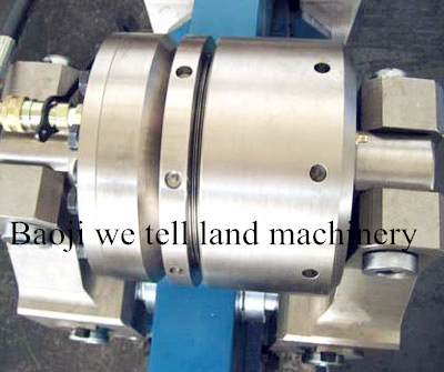
Wellhead throttle valve is the new generation of throttle and cut-off valve improved and developed by our company on the basis of gaining the national patent in 1992 and for the needs of oil and gas industry. The valve is a kind of multistage pressure reduction and high-pressure difference regulating valve and can be applied to control the high temperature, high pressure and high pressure difference as well as the flow and pressure of fluid containing solid particles. It adopts nozzle, labyrinth throttle to form the front and back multistage throttle; the valve spool and valve seat adopt hard and soft seal pairs to separate the sealing face and the throttling face, which has improved the throttling ability and sealing reliability of the valve and has the merits of reliable sealing, low noise, little vibration, throttle and cut-off pressure reduction, portable and flexible on and off, etc. The valve is especially suitable for the throttle and cut-off under high pressure. On the condition of high pressure, it possesses the function of pressure reduction and had a long service life. This series of product gains the national patent again after the secondary development .
ForH2S、CO2、CL and so on ...
DN(mm):DN32、 DN40、 DN50、 DN65
2.4 temp:-29℃~182℃(P grade )
70.0MPa 10000psi
The wellhead throttle valve is made up of nozzle, plunger-shaped spool, throttle value, valve body and valve rod, etc. It adopts valve seat nozzle, clathrate valve bush throttle structure and has the function of multistage throttle. The throttle pressure difference is big. The nozzle equipment is at the bottom of the valve seat; the valve spool has a balancing hole; the valve spool bush has an orifice. The valve spool and valve seat adopt hard and soft seal pairs to separate the sealing face and the throttling face and form the front and back three-state throttle, which has improved the throttling ability and sealing reliability
Electrical Land Rigs Features: | ||
■ | Choices of AC or DC electrical drilling rigs with capacities ranging from 3,000 to12,000meters | |
■ | Mechanical drilling rigs are offered | |
■ | All models available with Top Drive option | |
■ | Choices of many brand/types or Top Drives | |
■ | Various brand of generators and air sources available to fit customer’s specific application | |
■ | All weld lines are 100% inspected and X-rayed | |
■ | All rigs are modern designed and build with quality craftsmanship | |
■ | Rigs are well designed and over all balanced | |
■ | Rigs are designed to be assembled and disassembled quickly with minimum impact to the environment | |
■ | Buildings are insulated to protect the worker and instruments from the extreme weather | |
■ | Comply to API specification and guidelines | |
■ | API Spec Q1 | Quality Program Specification |
■ | SY/T5609/1999 | Type & Basic Parameters for Drilling Rig |
■ | API Spec 4F | Specification for Drilling and Workover Mast and Substructure |
■ | API Spec 8A | Specification for Drilling & Production Hoisting Equipment |
■ | API Spec 7 | Specification for Rotary Drilling Equipment |
■ | API Spec 16A | Specification for Blowout Prevention Equipment |
■ | API Spec 7F | Specification for Oilfield Chain and Sprocket |
■ | API Spec 9A | Specification for Wire Rope |
■ | API Spec 16C | Specification for Choke and Kill Devices |
■ | SY5305 | General Technical Requirements for Weldments of Oil & Petroleum Equipment |
■ | API Spec 9B | Recommended Practices for Selection, Maintenance, and Application of Wire Rope |
■ | API RP 53 | Recommended Practices of Control Systems of Blowout Prevention Equipment for Drilling Wells |
■ | API Spec 16D | Specification of Control Systems of Blowout Prevention Equipment for Drilling Wells |
■ | AISC | Steel Construction Manual(American Institute of Steel Construction the 8thedition) |
■ | SY5307 | General Technical Requirements for Assembly of Oil & Petroleum Equipment |
■ | SY5308 | General Technical Requirements for Painting of Oil & Petroleum Equipment |
■ | SY5309 | General Technical Requirements for Packaging of Oil & Petroleum Equipment |
■ | Click to download PDF catalogue | |
■ | Click to download sample rig plan | |
■ | Click to download sample rig manual |
DC Drilling Rig | |||||||||
Models | Unit | ZJ40/225DZ | ZJ50/315DZ | ZJ70/450DZ | ZJ90/585DZ | ||||
Nominal Drill Depth 4½” DP | m | 2500 - 4000 | 3500 - 5000 | 4500 - 7000 | 6000 - 9000 | ||||
Hook Load Rating KN | KN | 2250 | 3150 | 4500 | 5850 | ||||
Number of Travel Block Lines | 10 | 12 | 12 | 14 | |||||
Diameter of Wire Lines | mm | 32 (1¼“) | 35 (1⅜”) | 38 (1½”) | 42 (1⅝”) | ||||
Travel Block Sheave Diameter | mm | 1120 (44”) | 1270 (50”) | 1524 (60”) | 1524 (60”) | ||||
Swivel Center Diameter | mm | 75 (3”) | 75 (3”) | 75 (3”) | 75 (3”) | ||||
Rated Drawwork Power | HP | 1,000 | 1,500 | 2,000 | 3,000 | ||||
Drawwork Transmission | 4 + 4R | 4 + 4R | 4 + 4R | 4 + 4R | |||||
Rotary Table Opening | Inch Ø | 20 ½” | 27 ½” | 27 ½” | 37 ½” | 37 ½” | 49 ½” | ||
Rotary Table Speed | 2 | 2 | 2 | 2 | |||||
Mud Pump Power Rating | HP | 1,000 | 1,300 | 1,600 | 1,600 | 2,000 | |||
Number of Mud Pumps | 2 | 3 - 2 | 3 | 3 | |||||
Mast Working Height | m | 43 | 45 | 45 | 46 | ||||
Drill Floor Height | m | 7.5 | 7.5 | 9 | 9 | 10.5 | 10.5 | 12 | |
Drill Floor Clearance | m | 6.6 | 6.2 | 7.6 | 7.5 | 8.9 | 8.7 | 10 | |
Control Scheme | AC – SCR – DC One-on-Two w/Reserved Top Drive AC output |
AC VFD Drilling Rig | |||||||||
Models | Unit | ZJ40/225DB | ZJ50/315DB | ZJ70/450DB | ZJ90/585DB | ||||
Nominal Drill Depth 4½” DP | m | 2500 - 4000 | 3500 - 5000 | 4500 - 7000 | 6000 - 9000 | ||||
Hook Load Rating KN | KN | 2250 | 3150 | 4500 | 5850 | ||||
Number of Travel Block Lines | 10 | 12 | 12 | 14 | |||||
Diameter of Wire Lines | mm | 32 (1¼“) | 35 (1⅜”) | 38 (1½”) | 42 (1⅝”) | ||||
Travel Block Sheave Diameter | mm | 1120 (44”) | 1270 (50”) | 1524 (60”) | 1524 (60”) | ||||
Swivel Center Diameter | mm | 75 (3”) | 75 (3”) | 75 (3”) | 75 (3”) | ||||
Rated Drawwork Power | HP | 1,000 | 1,500 | 2,000 | 3,000 | ||||
Drawwork Transmission | 1 + 1R Stepless Drive | ||||||||
Rotary Table Opening | Inch Ø | 20 ½” | 27 ½” | 27 ½” | 37 ½” | 37 ½” | 49 ½” | ||
Rotary Table Speed | 1 stepless | 1 stepless | 1 stepless | 1 stepless | |||||
Mud Pump Power Rating | HP | 1,000 | 1,300 | 1,600 | 1,600 | 2,000 | |||
Number of Mud Pumps | 2 | 3 - 2 | 3 | 3 | |||||
Mast Working Height | m | 43 | 45 | 45 | 46 | ||||
Drill Floor Height | m | 7.5 | 7.5 | 9 | 9 | 10.5 | 10.5 | 12 | |
Under Drill Floor Clearance | m | 6.6 | 6.2 | 7.6 | 7.5 | 8.9 | 8.7 | 10 | |
Control Scheme | AC – SCR – VFD One-on-One w/Reserved Top Drive AC output |
Constituent of AC & DC Electric Drilling Rig | ||||||||
Models | ZJ40/225DB+Z | ZJ50/315DB+Z | ZJ70/450DB+Z | ZJ90/585DB+Z | ||||
Model | (kg) | Model | (kg) | Model | (kg) | Model | (kg) | |
Crown Block | TC225 | 5,670 | TC315 | 7,400 | TC450 | 9,500 | TC585 | 12,500 |
Traveling Block | YC225 | 3,805 | YC315 | 6,842 | YC450 | 8,135 | YC585 | 9,250 |
Hook | DG225 | 2,180 | DG315 | 3,410 | DG450 | 3,496 | DG585 | 3,600 |
Swivel + Air Spinner | SL225 | 2,560 | SL450 | 3,460 | SL450 | 3,460 | SL585 | 3,675 |
Rotary Table | ZP272 | 6,200 | ZP375 | 8,020 | ZP375 | 8,020 | ZP495 | 8,950 |
Drawwork (AC) | JC40DB | 37,000 | JC50DB | 52,000 | JC70DB | 61,000 | JC90DB | 72,000 |
Drawwork (DC) | JC40DZ | 37,000 | JC50DZ | 52,000 | JC70DZ | 61,000 | JC90DZ | 72,000 |
Mud Pumps | F1300 | 23,000 | F1600 | 24,500 | F1600 | 24,500 | 3NB2000 | 41,000 |
Mast | JJ225/43K2 | 52,600 | JJ315/45K | 66,000 | JJ450/45K7 | 76,200 | JJ585/46K | 87,650 |
Substructure | DZ225/7.5S | 101,700 | DZ315/9S | 142,000 | DZ450/10.5S | 195,000 | DZ585/12S | 221,000 |
Mechanical Drill Rig Specifications | |||||||
Rig Models | ZJ10B/59 | ZJ15B/90 | ZJ30/170 | ZJ40/225 | ZJ50/315 | ZJ70/450 | |
Drill Depth 4 ½” DP (m) | 500 – 1,000 | 800 – 1,500 | 1,600 – 3,000 | 2,500 – 4,000 | 3,500 – 5,000 | 4,500 – 7,000 | |
Rated Hook Load kN | 585 | 900 | 1,700 | 2,250 | 3,150 | 4,500 | |
Hook Speed m/sec. | 0.13 – 1.3 | 0.26 – 1.1 | 0.19 – 1.5 | 0.2 – 1.7 | 0.2 – 1.7 | 0.2 – 1.8 | |
Travel Block Lines | 8 | 8 | 10 | 10 | 12 | 12 | |
Drill Line Diameter mm | 22 | 26 | 29 | 32 | 35 | 38 | |
Fast Line Pull kN | 103 | 130 | 210 | 280 | 350 | 485 | |
Draworks | Model | JC-10B | JC-15B | JC-30 | JC-40 | JC-50 | JC-70 |
Power HP | 300 | 350 | 600 | 1,000 | 1,500 | 2,000 | |
Speed | 2 + 1R | 3 + 1R | 4 + 1R | 4 + 2R | 6 + 2R | 6 + 2R | |
Main Brake | Hydraulic Disc Brake or Band Brake | ||||||
Aux Brake | Eddy Current Brake + Pneumatic Disc Brake | ||||||
Crown Block | TC-60 | TC-90 | TC-170 | TC-225 | TC-315 | TC-450 | |
Traveling Block | YG-60 | YG-135 | YC-170 | YC-225 | YC-315 | YC-450 | |
Sheave OD inch | 23 ⅝” | 26” | 39 ½” | 44” | 50” | 60” | |
Hook | YG-60 | YG-135 | DG-250 | DG-250 | DG-315 | DG-450 | |
Swivel | Model | SL-80 | XSL-135 | XLS-170 | SL-250 | SL-450 | SL-450 |
Stem Ø | 2 ½” | 2 ½” | 2 ½” | 3” | 3” | 3” | |
Rotary Table | Opening | 17 ½” | 17 ½” | 20 ½” | 27 ½” | 37 ½” | 37 ½” |
Speed | 2 + 1R | 3 + 1R | 4 + 1R | 4 + 2R | 4 + 2R | 4 + 2R | |
Mast | Type | A | A | A | K | K | K |
Height, m | 29 | 31 | 41 | 43 | 45 | 45 | |
Load, kN | 585 | 900 | 1700 | 2250 | 3150 | 4500 | |
Sub Structure | Type | X | X | X | S | S | S |
Height, m | 3 | 3 | 3.8 | 6 | 7.5 | 9 | |
Clearance | 2.2 | 2.2 | 2.8 | 4.8 | 6.3 | 7.4 | |
Mud Pump | Model | F-800 | F-800 | F-1000 | F-1300 | F-1600 | F-1600 |
Number | 1 | 1 | 1 | 2 | 2 | 3 |