E24 Series Non-Inductive Wirewound Resistors KNP
Quick Details
1. Type : KNP Wirewound Resistor
2. Rated Power : 1/2W.1WS.1W.2WS.2W.3WS.3W.5WS.5W
3. Nominal resistance value : E24 Series
4. Resistance tolerance : J +/-5% G +/-2%
5. Shape : P type; M type :MB type : FK1 type : FK2 type : FKK type
6. T.C. : +/-350PPM/C Resistance Range: 0.05Ω~1KΩ
7. Operating temperature : -55℃~+255℃
• All welded construction
• Ceramic core
• Non-flammable cement coating
• Tinned copper-clad iron leads
(for axial parts)
• High power dissipation in small volume
• Ideal for pulse application
Description
This specification is available for Wirewound Resistor manufactured by Jackcon (HK) Industrial Limited ,it accords with RoHS test of Environment related substance requirement.
Application
Ideal for pulse application
Specification
1.Rated Power
Rated power is maximum power which can be continuously loaded at specified ambient temperature
70℃,as Table-1;however when the ambient temperature exceeds 70℃,rated power should be determined
from the derating curve of Fig.1.
Type
| Rated power
| Dielectric withstanding voltage | KNP Resistance Range(Ω) | NKNP Resistance Range(Ω) | |
Normal size | KNP1/2W, NKNP1/2W | 0.5W | 300V | 0.05Ω~1KΩ | 0.1Ω~680Ω |
KNP1W, NKNP1W | 1W | 350V | |||
KNP2W, NKNP2W | 2W | 350V | |||
KNP3W, NKNP3W | 3W | 400V | |||
KNP5W, NKNP5W | 5W | 400V | |||
Small size | KNP1WS, NKNP1WS | 1W | 300V | 0.05Ω~1KΩ | 0.1Ω~680Ω |
KNP2WS, NKNP2WS | 2W | 350V | |||
KNP3WS, NKNP3WS | 3W | 350V | |||
KNP5WS, NKNP5WS | 5W | 400V |
Figure 1 Power derating curve
The rated voltage shall be the D.C. or A.C.(R.M.S. at power frequency) voltage which corresponds
the rated power and the value of which is calculated from the formula below.
E=√(P×R) Where E: Rated voltage(V)
P: Rated power(W)
R: Nominal resistance(Ω)
Operating Temperature Range:-55℃~+255℃
2.Construction
NO | Item | Material |
1 | Ceramic core | High alumina ceramic is used. |
2 | Resistor element | The resistor element shall consist of Resistance wire(Exemple:CN49W Φ1.0mm) . |
3 | Terminal | Tinned iron cap. |
4 | Connection | The lead wire,which is plated with solder,shall be mounted to the caps by welding process. |
5 | Lead wire | Soldered or tinned annealed wire. |
6 | Finishing painting | Silicon resin is used. Accord with UL-94V-0 Nonflammable specification. |
7 | Indication | Color code. |
1) Terminal caps :The caps shall be securely connected with the resistor element electrically and mechanically.
2) Resistor body color
Table-2
Normal size | Small size | ||
Type | Color | Type | Color |
KNP1/2W,NKNP1/2W, KNP1W,NKNP1W KNP2W,NKNP2W, KNP3W,NKNP3W | Gray | KNP1WS,NKNP1WS, KNP2WS,NKNP2WS, KNP3WS,NKNP3WS KNP5WS,NKNP5WS | Pink |
3) Indication The indication shall be satisfied with [4. Indication].
3. Characteristics
Table-3
Item | Performance | Test methods(Conform to JIS C 5202) |
Temperature Coefficient | ±350PPM/℃ (±500PPM/℃<1Ω) | Comply with 5.2 R1-R0/R0(T1-T0)*10 6(PPM/C)
R0:Resistance value at room temp.( T0). R1:Resistance value at room temp.plus 100℃(T1) |
Short time overload | Within ±(2%+0.05Ω). No evidence of mechanical damage. | Comply with 5.5 Rated voltage×2.5 times,5s But not to exceed maximum overload voltage. (See table-1) |
Item | Performance | Test methods(Conform to JIS C 5202) | |||||||||
Insulation Resistance | 104MΩ or more. | Comply with 5.6 V-block method Resistor shall be tested at DC 500V for 60 seconds. | |||||||||
Dielectric Withstanding Voltage |
No evidence of flashover mechanical damage,arcing or insulation breakdown. | Comply with 5.7 Constant pressure, V-block method Resistor shall be tested at AC potential respectively for 60 seconds.(See table-1) | |||||||||
Pulse overload | Within ±(2%+0.05Ω) | Comply with 5.8 Rated voltage X 4 times, 10000 cyc.(1s ON, 25s OFF) But not to exceed maximum pulse voltage.(See table-1) | |||||||||
Terminal strength | No evidence of mechanical damage. | Comply with 6.1
Torsion strength:To bend the lead wire at the point of about 6mm~6.5mm from resistor body. about 0.75mm curvature radii to 90°then catch the wire at 1.2±0.4mm apart from the bend point end and turn it ( clockwise ) by 360 degrees perpendicular to the resistor axis at speed of same 5 seconds per turn, and do the same counterclockwise again which constitute a whole turn. Repeat the turn for 2 times without causing any break and looseness. |
Item | Performance | Test methods(Conform to JIS C 5202) |
Resistance to soldering heat | Within ±(1%+0.05Ω) No evidence of mechanical damage. | Comply with 6.4 350±10℃, 3±1s After test leave for 0.5h. |
Solderability | Covered with new solder by 95% at least. | Comply with 6.5 Test temperature of solder:255±5℃ Dipping time in solder:3±1.0 s |
Resistance to solvent | No deterioration of protective coating and markings. | Comply with 6.9 Specimens shall be immersed in a bath of isoproalcohol completely for 3 minutes with ultrasonic. |
Temperature cycle | Within ±(1%+0.05Ω) No evidence of mechanical damage. | Comply with 7.4 Low side:-55℃/30min, Room temp.:10 to 15min High side:80℃/30min, Room temp.:10 to 15min 5 cycles |
Load life in humidity | Within ±(5%+0.05Ω) | Comply with 7.9 40±2℃, 90 to 95%RH, 1000h Rated voltage (90 min ON, 30 min OFF) |
Load life | Within ±(5%+0.05Ω) | Comply with 7.10 70±3℃, 1000h Rated voltage (90 min ON, 30 min OFF) |
4. Indication
Color | 1st figure | 2nd figure | Multiplier | Tolerance | Distinguish | |
Black | 0 | 0 | 100 |
|
| . KNP type in ‘Black’, NKNP type in ‘Green’. |
Brown | 1 | 1 | 101 | ±1% | (F) | |
Red | 2 | 2 | 102 | ±2% | (G) | |
Orange | 3 | 3 | 103 |
|
| |
Yellow | 4 | 4 | 104 |
|
| |
Green | 5 | 5 | 105 |
|
| |
Blue | 6 | 6 | 106 |
|
| |
Violet | 7 | 7 | 107 |
|
| |
Gray | 8 | 8 |
|
|
| |
White | 9 | 9 |
|
|
| |
Gold |
|
| 10-1 | ±5% | (J) | |
Silver |
|
| 10-2 | ±10% | (K) | |
Plain |
|
|
|
|
|
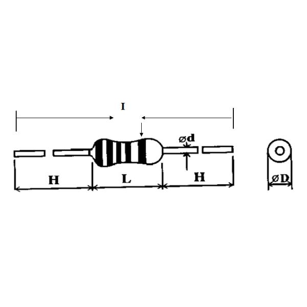
5. External dimensions
5.1 P Type
The 5th color band; KNP type in ‘Black’, NKNP type in ‘Green’
Unit: mm
Type | Dimensions | |||||
Normal Size | Small Size | I±2.0 | L±1.0 | ψD | ψd±0.05 | H±2.0 |
KNP1/2W, NKNP1/2W | KNP1WS, NKNP1WS | 60 | 9.0 | 3.2±0.5 | 0.50 | 28 |
KNP1W, NKNP1W | KNP2WS,NKNP2WS | 60 | 11.5 | 4.5±1.0 | 0.68 | 25 |
73 | 11.5 | 4.5±1.0 | 0.68 | 31 | ||
KNP2W, NKNP2W | KNP3WS,NKNP3WS | 60 | 15.5 | 5.0±1.0 | 0.68 | 23 |
81 | 15.5 | 5.0±1.0 | 0.68 | 33 | ||
KNP3W, NKNP3W | KNP5WS, NKNP5WS | 94 | 17.5 | 6.0±1.0 | 0.68 | 38 |
KNP5W,NKNP5W | 94 | 24.5 | 8.0±1.0 | 0.68 | 35 |
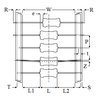
5.2 Axial Lead Taping
Txx Type
unit:mm
Type | Taping | Dimensions | ||||||||||
Normal Size | Small Size | L | W | P | L1-L2 Max. | T | Z Max. | R Max. | t Max. | e Max. | S Max. | |
KNP 1/2W | KNP 1WS | T52 | 9.0±1.0 | 52±1.0 | 5±0.5 | 1.0 | 6±0.5 |
|