Marine Well Installation Rudder Propeller
1.Introduction
Our factory is a specialized factory for manufacturing special marine propulsion units, mainly Controllable pitch propeller(CPP), Tunnel thruster (TT) and Rudder propeller(RP). It was founded in 1975 and has a history of more than 30 years. As for the designing and manufacturing of the marine propulsion units, it has rich experience and introduced advance technology of Controllable pitch propeller from Kamewa of Sweden and Rudder propeller from Schottel of Germany. Not only for the technic and variety but also the quantity and service for consumers has a solid foundation.
2.Marine Rudder Propeller
The rudder propeller is one series of our products.We introduced the rudder propeller technology from SCHOTTEL of Germany in 1986. The rudder propeller made by us has been approved by the China Classification Society and other international Classification Societies. And the products have been successfully installed, used and served on the ships. They are sailing in oceanic area of home and abroad. Rudder propeller is today used for all types and size of ships.We can provide with a series of specifications of Rudder propeller.
The propeller can be freely steered through 360 degrees around the stem. Therefore the Rudder propeller is a combined propulsion and steering unit, sothat the full thruster is available in any direction for the ship.
If the prime engine is electric or hydraulic motor, the upper gearbox can be eliminated. The electric or hydraulic motor can be vertically mounted on the fixed flange and the power will be transmitted through a bevel gear in lower gearbox on to the propeller(L-drive).
The rudder propeller can be operated by mechanical, hydraulic or electric-hydraulic unit, and can be in activ service as main propulsion, auxiliary propulsion and dynamic positioning of the ship, which are usually used in tugs, puch boats, ferry boats and barges etc. Now the company is developing higher power RP to satisfy requirements from market.
There are three installation types: Transom installation, Well installation, Deck installation.
3.Well Installation Rudder Propeller
The well installation is especially for tugs, ferries, well station, floating dock and survey ships.
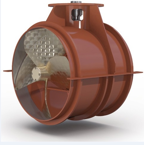
Our rudder propeller is mounted in the well.The stem length varieswith the requirement of the application. The top mounting plate of the well should, if at all possible, be above the waterline so that the Rudder Propeller can be installed and removed when the ship is floating.
Well installation varies with the distance between the Rudder Propeller and the diesel engine.When the engine room is very small, the Rudder Propeller can be near to the diesel engine and suitable for application in long-range transmission between diesel engine and rudder propeller.
4.General parameter of parts of our rudder propeller
Type | SRP12 | SRP50/51 | SRP100/103 | SRP152/151 | SRP300/151 | SRP300/226 | SRP300/300 | SRP352/300 | |
Input Power Kw/HP | 45/61 | 100/135 | 210/285 | 300/400 | 255/347 | 350/476 | 480/650 | 490/666 | |
Max Input Torque N.m | 200 | 420 | 850 | 1675 | 2500 | 2050 | 2800 | 5200 | |
Max Imput Speed r/min | 2300 | 2500 | 2350 | 2000 | 1000 | 1800 | 1800 | 1000 | |
Reduction Ratio | 1.93 | 2.5 | 2.68 | 3.46 | 2.37 | 3.34 | 3.96 | 2.2 | |
Propeller Dia.mm | Max | 500 | 822 | 950 | 1150 | 1150 | 1350 | 1550 | 1550 |
Min | 700 | 900 | 1100 | 1250 | |||||
PAL Length mm | Max | 2250 | 2800 | 2800 | 4250 | 4400 | 4750 | 4750 | 4750 |
Min | 350 | 875 | 980 | 1400 | 1400 | 1750 | 1750 | 2000 | |
Weight KG | 65 | 190 | 300 | 1370 | 2000 | 2100 | 3580 | ||
PAL per 100mm extension kg | 8 | 9 | 20.4 | 40 | 40 | 40 | 40 | 40 | |
PAL The length between the center line of transmission flange and the center line of the propeller | |||||||||
Type | SRP45 | SRP85 | SRP138 | SRP180 | SRP226 | SRP280 | SRP310 | SRP330 | |
Input Power Kw/HP | 100/135 | 210/285 | 260/354 | 340/462 | 350/476 | 480/650 | 580/783 | 620/843 | |
Max Input Torque N.m | 450 | 850 | 1380 | 1800 | 2260 | 2800 | 3070 | 3300 | |
Max Imput Speed r/min | 2500 | 2350 | 2000 | 1800 | 1800 | 1800 | 1800 | 1800 | |
Reduction Ratio | 2.5 | 2.68 | 3.01 | 3.46 | 3.34 | 3.96 | 3.718 | 4.04 | |
Propeller Dia.mm | Max | 800 | 950 | 1100 | 1150 | 1350 | 1550 | 1550 | 1500 |
Min | 500 | 700 | 9000 | 900 | 1100 | 1250 | 1250 | 1300 | |
PAL Length mm | Max | 2800 | 2800 | 4250 | 4400 | 4750 | 4750 | 5000 | 5000 |
Min | 875 | 980 | 1100 | 1100 | 1750 | 1750 | 1700 | 1700 | |
Weight KG | 190 | 400 | 1200 | 1450 | 2000 | 2100 | 2500 | 2800 | |
PAL per 100mm extension kg | 9 | 20.4 | 20.7 | 40 | 40 | 40 | 45 | 45 | |
PAL The length between the center line of transmission flange and the center line of the propeller |
5.Type Choosing of rudder propeller
Max imput torque of Rudder Propeller decides capacity of its transmit power of prime mover.The kind of rudder propeller operation, the type of prime mover and the sort of vessel may influence the actual allowable imput torque figure. It is recommended to consult with our technical staff before selecting the Rudder Propeller size. To select a proper Rudder Propeller, the output torque Mp of the prime mover(general diesel engine,hydraulic motor or electric motor) is the most important factor which is calculated as below:
Each type of Rudder Propeller has a specific allowable design torque,according to the norml engineering safety factors. Because of our experience, we have considered that this design torque cann't be the last gist in the selection procedure. Serious consideration has to be given to the various service conditions, resulting in a service factor Sf with which the nominal design torque has to be corrected as the formulary:
Sf= fz * fi * fs
Our rudder proppeller service factors normally satisfy the regulations of Classification Societies. For ice class SRP type, it requires service factors that have to be between 0.33 and 0.67. The definete factors for special installation hav to be decided by us.
fz | Mumber of operation hours per year |
1.00 | Up to 3000 hours |
0.95 | 3000-5000 hours |
0.90 | Over 5000 hours |
f1 | Load condition |
1.00 | Intermittent Load |
0.95 | Up to 50% full load |
0.90 | Continuous full load |
fo | Overload condition |
1.00 | No engine overload |
0.95 | Engine overload 10% |
0.90 | More than 10% overload |
fs | Field of operation |
1.10 | Dynamic positioning |
1.00 | Inland waterways |
0.95 | Inland waterways with limited depth |
0.95 | Limited field of operation |
0.90 | Unlimited field of operation |
Sf=0.75: Full power continuous rating 24 hours service(container ships,push tugs)
Sf=0.9: intermittent service with eventual full load( harbor tugs, floating crane)
Sf=1.00: Auxiliary installations ( tunnel thruster, Dp-installations)