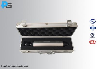
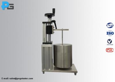
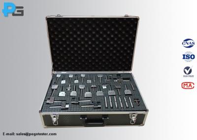
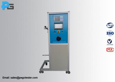
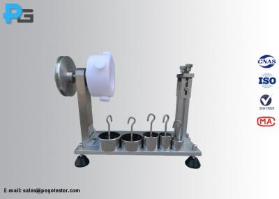
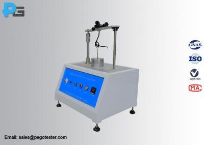
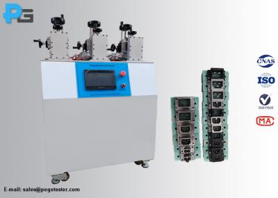
The appliance couplers withdrawal force testing equipment is designed according to IEC60320-1 figure 3 and figure 4 and clause 16, for verification of the maximum and minimum withdrawal force of connector/appliance outlet. The minimum withdrawal force is verified by inserting the test pin gauge to each individual connector/appliance outlet. The equipment consists of control cabinet, mounting plate, heating device, appliance inlets/plug connector, mass hook, supplementary mass and principal mass. The height of the frame of the device is 550mm, and the distance between the axes of the two columns is 150mm. The appliance inlet / plug connector gauges made of hardened steel with roughness not exceeding 0.8mm.
Maximum withdrawal force: apply the maximum withdrawal force specified in the standard (the total force of the principal mass, the supplementary mass, the hook, and the appliance inlets/plug connector), the connector / appliance outlet shall not remain in the appliance inlet / plug connector.
* For testing the appliance couplers for hot conditions or very hot conditions, the heating function should be turned on and the maximum withdrawal force test should be started after reaching the specified temperature.
Minimum withdrawal force: Hand-held the specimen, and insert the test pin gauge of the minimum withdrawal force specified in the standard ( the total mass of the pin should be equal to the value specified in the standard) into each individual connector / appliance outlet, the gauge shall not fall from the contact assembly within 3s.
Multi-pin gauge (for maximum withdrawal force test) | As per the standard sheet of connector/appliance outlet | ||||||||||||
Single pin gauge (for minimum withdrawal force test) | As per the standard sheet of connector/appliance outlet | ||||||||||||
Heating temperature | R.T.~180℃ (pre-settable) | ||||||||||||
Mass configuration (maximum withdrawal force) | 45N*1 5N*1 4N*1, 6N*1
| ||||||||||||
Mass configuration (minimum withdrawal force) | 1.5N*1, 2N*1 Notes: the mass of the single pin is counted into the corresponding mass | ||||||||||||
Working power | AC220V±10%/50-60Hz | ||||||||||||
Working condition | Temperature: 5-35℃, R.H.: 30%~90% | ||||||||||||
Dimension and weight | W400mm*D300mm*H800mmm/40KG |
Table 5- Maximum and Minimum Withdrawal Forces
Type of connetor/appliance outlet | Withdrawal force (N) | |
Multi-pin gauge Maximum | Single-pin gauge Minimum | |
0.2A, 2.5A, 6A and 10A | 50 | 1.5 |
16A | 60 | 2 |
The withdrawal force test device cconsists of frame, control cabinet, the mounting plate, heating device, appliance inlet/plug connector (multi-pin gauge maximum and single-in gauge), clamp, supplementary mass and principal mass. The frame is mate of steel, the supplementary mass. And the principal mass and the appliance inlet/plug connector (multi-pin gauge for maximum extraction test and single-pin gauge for minimum extraction test) are made of S16 anti-corrosion mirror steel which with magnetic and rust-proof characteristic. The appliance inlet/plug connector (multi-pin gauges) and single-pin gauges can be customized as per the standard sheet of connector/appliance outlet.