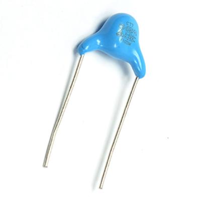
Safety Ceramic Disc Capacitor X1 Y1 2.2nF 400VAC P10mm Y5V For Power Filter
Specifications
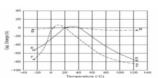
B: Y5P E: Y5U F: Y5V
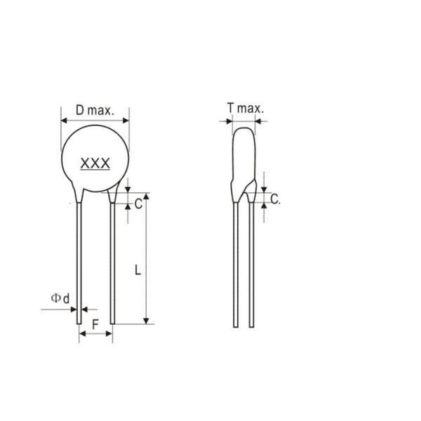
Dimensions (mm)
D±1.0 | T±1.0 | L min | F±0.8 | φ±0.05 | c Max |
7.0 | 4.0 | 20.0 | 10.0 | 0.6 | 2.0 |
Test Condition
Test must be in the standard condition( Temperature 15~30℃, Relative humidity 45~75%, air pressure 86~106Kpa)
Unless otherwise specified, capacitance must be under base conditions in case of doubt of measurement results and special requirements (Temperature 25±2℃, Relative humidity 60~70%, air pressure 86~106Kpa). Apply to X1Y1 and X1Y2.
No. | Item | Standard | Test Condition | |||||||||||||||||||||||||||
1 | Appearance and size | There is no obvious defect in appearance shape, the size is within the standard range | Capacitance must be visually checked for obvious defects. Dimensions are measured with vernier calipers. | |||||||||||||||||||||||||||
2 | Printing | Clear and could be recognized. | Visual Check. | |||||||||||||||||||||||||||
3 | Capacitance | Within the specified tolerance range | Capacitance and Dissipation factor must be tested under the temperature 20℃, and 11KHz, 1±0.1V | |||||||||||||||||||||||||||
4 | (D.F.) Dissipation Factor | ≤200×10-4 | ||||||||||||||||||||||||||||
5 | (I.R.) Insulation Resistance | ≥10000MΩ | Insulation resistance must be tested after charging 60±5 seconds under voltage 500±50V. | |||||||||||||||||||||||||||
6 | Dielectric strength | Between two terminals | There is no breakdown or arc. | (The charge and discharge current is not greater than 50mA) The capacitor is added voltage in the below table, after 60s, there is no damage, <Table 1>
| ||||||||||||||||||||||||||
The body insulation | There is no breakdown or arc. | First, the terminals of the capacitor are twisted together, and then, as shown in the figure on the right, the metal foil is wrapped around the capacitor's body 3-4mm away from the terminal. Then, the capacitor is inserted into the container holding a metal ball with a diameter of 1mm. Finally, the AC voltage as shown in table 2 is applied for 60 seconds. <Table 2>
| ||||||||||||||||||||||||||||
7 | Temperature Characteristics |
Temperature Range: -25 ~ +125℃ | The capacitor must be tested under temperature as below Table 3 <Table 3>
| |||||||||||||||||||||||||||
8 | Resistance to soldering heat | Appearance | No damage | The conductor of the capacitor must be immersed in the solder for 5 + / -0.5 seconds. Dip depth 2.5 mm from wire root. Soldering temperature: 250±5℃ 24±2hrs later, make testing.
| ||||||||||||||||||||||||||
Capacitance change rate | ΔC/C≤10% | |||||||||||||||||||||||||||||
9 | Vibration resistance | Appearance No damage | Frequency 10~500Hz, total amplitude to 0.75mm, time 6hrs | |||||||||||||||||||||||||||
10 | Humidity | Appearance | No damage | The time was 500+24- 0h, the temperature was 40±2℃ and the temperature was 90 ~ 95%. After the test was completed, the temperature was restored to 24±2h at room temperature. | ||||||||||||||||||||||||||
Capacitance change rate | ΔC/C≤15% | |||||||||||||||||||||||||||||
I.R. Insulation Resistance | ≥3000MΩ | |||||||||||||||||||||||||||||
Loss Tangent | △tanδ≤80×10-4 | |||||||||||||||||||||||||||||
11 | Durability | Appearance | No damage | The temperature was 85±2℃, the duration was 1000h and the rated voltage was 1.7 times. After the test, the temperature was restored to 24±1h
| ||||||||||||||||||||||||||
Capacitance change rate | ≤20% | |||||||||||||||||||||||||||||
I.R. Insulation Resistance | ≥3000MΩ | |||||||||||||||||||||||||||||
Loss Tangent | △tanδ≤80×10-4 | |||||||||||||||||||||||||||||
12 | Lead Weldability | Wet lead solder, free flow to indicate good tin coating | After the capacitor leads are immersed in 25% alcohol rosin solution, they are immersed in solder with melting temperature of 235±5℃ and 2± 0.5s into the depth of 2 ~ 2.5mm away from the porcelain body. | |||||||||||||||||||||||||||
13 | Flame retardant test | Apply flame duration 30S, residual flame duration ≤10S. | Apply flame duration 30S, residual flame duration ≤10S. | |||||||||||||||||||||||||||
14 | Impulse test | The capacitor shall have no failure | Add the capacitor to the pulse voltage y1:8kvdc and y2:5kvdc, and make 24 pulses of the same polarity, at a time interval of not less than 10S |
Our series of strong products of capacitors and resistors can be divided into below types:
★ Ceramic Disc Capacitor( low and high voltage, Y1/Y2 safety )
★ Multilayer Ceramic Capacitor( radial, axial and SMD )
★ Film Capacitor( Mylar, MKT, MKP, X2, CBB60, CBB61, CBB65, CL21-Box, CBB-BOX, CL20, CBB20, CBB81, etc. )
★ Aluminum Electrolytic Capacitor(SMD, Radial , Axial, Snap-in , Screw Terminal, etc. )
★ Tantalum Capacitor(SMD, Radial , Axial )
★ Super Capacitor( Coin Type, Cylindrical Type, Module Type)
★ Mica Capacitor
★ Trimmer Capacitor
★ SMD Resistors
★DIP TYPE Resistors( KNP, CF, MF, MOF, ect,)
★ Cement Resistors
★ Leadless Resistors( MLEF)
★Power Resistor
Any more details, kindly contact us freely!