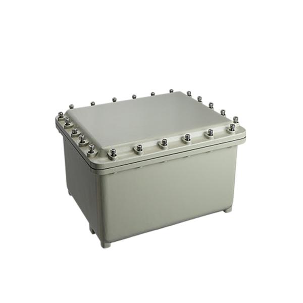
Customized Junction Box Special Junction Box Explosion Proof EJB Series Junction Box-19
ATEX and IECEx certified for use in hazardous areas.
Body and cover are made of marine grade copper free aluminum and light alloy.
Internal mounting plates are made of hot dip galvanized steel or stainless steel.
Stainless steel flame-proof tighten screws.
Stainless steel hinges on the long side.
Surface electrostatic powder spraying treatment.
Silicone rubber gasket on the cover
For safe used in Zones 1 and 2 potentially explosive gas and Zones 21 and 22 dust atmospheres.
Marking ATEX
II 2G Ex db IIB Gb
II 2D Ex tb IIIC Db
Marking IECEx
Ex db IIB Gb
Ex tb IIIC Db
UL Standards
Class I, Division 1, Groups C, D
Class I, Division 2, Groups C, D
Class II, Division 1, Groups E, F, G
Class II, Division 2, Groups F, G
Class III
EN IEC 60079-0, EN IEC 60079-1,EN IEC 60079-31
Ambient temperature
-60℃ to+60℃
EJB-A; EJB: Explosion-proof junction box; A: Shape code,
Table 1
Enclosure Type | Dimension Code(mm) | |||||||
A | B | C | D | E | F | G | H | |
EJB-I | 350 | 300 | 200 | 164 | 290 | 240 | 220 | 270 |
EJB-II | 450 | 350 | 210 | 159 | 378 | 278 | 255 | 355 |
EJB-III | 560 | 450 | 280 | 223 | 488 | 378 | 360 | 470 |
Note: The dimension in the bracket is only for the reference
Note: Plane A, B, C and D in the figure indicate the direction of the inlet. Maximum allowable number of openings for threads of the same specification. The introduction device is equipped with a rubber gasket to prevent loosening.
Table 2 (C and D Plane)
Enclosure Type | Drilling Area L-B(mm) | Qunatity Allowed Entries For Size | ||||||
½NPT M20 | ¾NPT M25 | 1 NPT M32 | 1¼NPT M40 | 1½NPT M50 | 2 NPT M63 | 2½NPT M75 | ||
EJB-I | 240*110 | 15 | 10 | 8 | 6 | 3 | 2 | 2 |
EJB-II | 320*110 | 21 | 12 | 11 | 10 | 4 | 3 | 3 |
EJB-III | 320*110 | 21 | 12 | 11 | 10 | 4 | 3 | 3 |
Table 3 (A and B Plane)
Enclosure Type | Drilling Area L-B(mm) | Qunatity Allowed Entries For Size | ||||||
½NPT M20 | ¾NPT M25 | 1 NPT M32 | 1¼NPT M40 | 1½NPT M50 | 2 NPT M63 | 2½NPT M75 | ||
EJB-I | 180*110 | 12 | 7 | 6 | 6 | 2 | 2 | 1 |
EJB-II | 220*115 | 15 | 8 | 8 | 6 | 3 | 2 | 2 |
EJB-III | 320*160 | 28 | 18 | 17 | 14 | 8 | 3 | 2 |
Table 4
Entry Size | Minimum Spacing Of Entry mm(inch) | ||||||
NPT Metric | ½NPT M20 | ¾NPT M25 | 1 NPT M32 | 1¼NPT M40 | 1½NPT M50 | 2 NPT M63 | 2½NPT M75 |
½NPT M20*1.5 | 46 (1.81) | 49(1.93) | 52(2.05) | 59(2.32) | 61(2.40) | 76(2.99) | 86(3.39) |
¾NPT M25*1.5 | 52(2.05) | 55(2.17) | 64(2.52) | 69(2.72) | 79(3.11) | 89(3.50) | |
1 NPT M32*1.5 | 58(2.28) | 65(2.56) | 72(2.83) | 82(3.23) | 92(3.62) | ||
1¼NPT M40*1.5 | 72(2.83) | 79(3.11) | 89(3.50) | 99(3.90) | |||
1½NPT M50*1.5 | 85(3.35) | 95(3.74) | 106(4.17) | ||||
2 NPT M63*1.5 | 105(4.13) | 115(4.53) | |||||
2½NPT M75*1.5 | 126(4.96) |
Table 5
No. | ANSI/ASME B1.20.1 | ISO-965-1 and ISO 965-3 |
1 | ½ NPT | M20 |
2 | ¾ NPT | M25 |
3 | 1 NPT | M32 |
4 | 1¼ NPT | M40 |
5 | 1½ NPT | M50 |
6 | 2 NPT | M63 |
7 | 2½ NPT | M75 |
Note: The minimum number of engagement threads of NPT is 5. Thread shape and fit grades shall comply with the intermediate or precision tolerance grades specified in ISO 965-1 and ISO 965-3. The minimum number of threads engaged is 8.
Table 6
The table of maximum number of possible enclosure cable entries | ||||||
Drawing Number | EJB-I | EJB-II | EJB-III | |||
NPT Metric | AB | CD | AB | CD | AB | CD |
½NPT M20*1.5 | 16 | 20 | 18 | 27 | 18 | 26 |
¾NPT M25*1.5 | 9 | 12 | 12 | 18 | 15 | 21 |
1 NPT M32*1.5 | 9 | 12 | 11 | 15 | 14 | 18 |
1¼NPT M40*1.5 | 5 | 6 | 6 | 8 | 8 | 10 |
1½NPT M50*1.5 | 4 | 6 | 5 | 7 | 6 | 6 |
2 NPT M63*1.5 | 2 | 3 | 3 | 4 | 3 | 4 |
2½NPT M75*1.5 | 1 | 2 | 2 | 2 | 2 | 3 |
Note: The opening size of the distribution box is the cable gland specification. The selection of cable gland specifications should be selected according to the outer diameter of the cable and the actual conditions of the use environment.
Table 7
Enclosure Type | Drilling Area E-F(mm) | Max Operators Permitted |
EJB-I | 230*180 | 12 |
EJB-II | 310*210 | 20 |
EJB-III | 420*310 | 35 |
Note: Opening Distance Reference Spacing Table of Openings
Note:
a. The size of the window is determined by the instrument selected by the customer, the limit temperature of window is -60℃ to +180℃.
b. Spacing between lower boundary of windows and threaded holes are not refer to spacing table of openings.
c. Sufficient length of width of flameproof joint and installation position shall be reserved.
Explosion-proof treatment of cover and observation window shall comply with
EN IEC 60079-1 2014 explosive atmospheres –Part 1: equipment protection by flame proof enclosures "d".
Table 8
Enclosure Type | A(mm) | B(mm) |
EJB-I | 25 | 10 |
EJB-II | 25 | 10 |
EJB-III | 25 | 10 |
Table 9
Type | Yield Strength (Mpa) | Torque applied(Nm) |
M6X 16-6g | ≥450Mpa | 18 |
M8X 35-6g | 43 | |
M10X 35-6g | 84 |
Table 10
Heat Table(Total heat dissipated by components | |||
Model | Maximum Dissipated Power(W) | ||
T4/T130℃ | T5/T95℃ | T6/T80℃ | |
EJB-I | 350 | 200 | 130 |
EJB-II | 500 | 280 | 160 |
EJB-III | 652 | 350 | 200 |
Table 11
The corresponding table of the number of terminal blocks | |||
Drawing Number | EJB-I | EJB-II | EJB-III |
2.5mm² | 72 PCS | 100 PCS | 140 PCS |
4mm² | 64 PCS | 86 PCS | 116 PCS |
6mm² | 50 PCS | 66 PCS | 90 PCS |
10mm² | 24 PCS | 52 PCS | 72 PCS |
16mm² | 20 PCS | 25 PCS | 60 PCS |
35mm² | 10 PCS | 15 PCS | 224 PCS |
95mm² | 5 PCS | 10 PCS | 18 PCS |
120mm² | - | 5 PCS | 5 PCS |
185mm² | - | - | 5 PCS |
240mm² | - | - | 5 PCS |
300mm² | - | - | 5 PCS |
Q1. Do you have any MOQ limit for led light order?
A: Low MOQ, 1pc for sample checking is available.
Q2. How do you ship the goods and how long does it take to arrive?
A: Ship by DHL, UPS, FedEx or TNT. It takes 3-5 days to arrive. Airline and sea shipping also optional