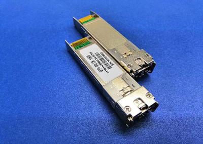
Multimode 850nm SR 10G SFP Module SFP+ MMF Up To 100m Dual LC Fiber Module
Applications
1ⅹInfiniBand QDR, DDR, SDR
High-performance computing clusters
10 Gigcabit Ethernet
4G and 8G Fibre Channel Applications
Servers, switches, storage and host card adapters
PRODUCT FEATURES
Operating case temp
Commercial: 0°C to +70 °C
RoHS compliant
Password protection for A0h and A2h
Support 10GBASE-SR/10G Fiber Channel application
Compliant to SFP+ Electrical MSA SFF-8431
Compliant to SFP+ Mechanical MSA SFF-8432
Multi rate of up to 11.3Gbps
Transmission distance up to 150m (OM3)
+3.3V single power supply
Low power consumption
PRODUCT DESCRIPTION
SFP+10G-SR MultiMode Transceiver is SFP+ modules for duplex data communication as 8G Fiber Channel, IEEE 802.3ae 10G Base-LR/LW It is SFP+ 20-PIN Connector to allow hot plug capability.
Digital diagnostic monitor functions are available via I2C. This module is designed and operates at 850nm wavelength.
Optical module also be called optical fiber module, the translation should be transceiver module. The function of the optical module is the photoelectric conversion, and the transmitter converts the electrical signal into the optical signal. After the transmission through the optical fiber, the receiving end converts the optical signal into the electrical signal. SFP+ is a kind of optical module.
Absolute Maximum Ratings
Table2- Absolute Maximum Ratings
Parameter | Symbol | Min. | Typical | Max. | Unit | Notes |
Supply Voltage | Vcc3 | -0.5 | - | +3.6 | V | |
Storage Temperature | Ts | -40 | - | +85 | °C | |
Operating Humidity | RH | +5 | - | +85 | % | 1 |
Note1: No condensation
Recommended Operating Conditions
Table 3- Recommended operating Conditions
Parameter | Symbol | Min. | Typical | Max. | Unit | Notes | |
Operating Case Temperature | TC | 0 | - | +70 | °C | ||
Power Supply Voltage | Vcc | 3.14 | 3.3 | 3.47 | V | ||
Power Supply Current | Icc | - | - | 150 | mA | ||
Power Dissipation | Pd | - | - | 0.6 | W | ||
Bit Rate | BR | - | 10.3125 | - | Gbps |
Electrical Characteristics
Table 4- Electrical Characteristics
Parameter | Symbol | Min. | Typ. | Max. | Units | Notes | ||||
Transmitter | ||||||||||
Differential Data Input Swing | Vin,P-P | 200 | - | 1600 | mVPP | |||||
Input Differential Impedance | ZIN | 90 | 100 | 110 | Ω | |||||
Tx_Fault | Normal Operation | VOL | 0 | - | 0.8 | V | ||||
Transmitter Fault | VOH | 2.0 | - | VCC | V | |||||
Tx_Disable | Normal Operation | VIL | 0 | - | 0.8 | V | ||||
Laser Disable | VIH | 2.0 | - | VCC+0.3 | V | |||||
Receiver | ||||||||||
Differential Date Output | Vout | 370 | - | 1600 | mV | |||||
Output Differential Impedance | ZD | 90 | 100 | 110 | Ω | |||||
Output Rise Time(20-80%) | TR | 24 | - | - | ps | |||||
Output Fall Time (20-80%) | TF | 24 | - | - | ps | |||||
Rx_LOS | Normal Operation | VOL | 0 | - | 0.8 | V | ||||
Lose Signal | VoH | 2.0 | - | VCC | V |
Optical Characteristics
Table 5-Optical Characteristics
Parameter | Symbol | Unit | Min | Typ | Max | Notes |
Optical transmitter Characteristics | ||||||
Bit Rate | BR | Gbps | 9.953 | 10.3125 | 11.3 | |
Center Wavelength Range | λc | nm | 820 | 850 | 880 | |
RMS spectral width | △λ | nm | 0.45 | |||
Average Launch power Tx_off | Poff | dBm | - | - | -45 | |
Launch Optical Power | P0 | dBm | -6.5 | -1 | 1 | |
Extinction Ratio | ER | dB | 3 | - | - | |
Jitter P-P | JP | ps | - | - | 27 | |
Jitter RMS | JR | ps | - | - | 5 | |
Optical Rise/Fall time | Tr/tf | ps | - | - | 100 | |
Optical Receiver Characteristics | ||||||
Bit Rate | BR | Gbps | 9.953 | 10.3125 | 11.3 | |
Receiver Sensitivity | RS | dBm | - | - | -9.9 | 2 |
Overload Input Optical Power | PIN | dBm | -1 | - | - | 2 |
Center Wavelength Range | λc | nm | 820 | - | 880 | |
LOS | LOSD | dBm | - | - | -12 | |
LOSA | -26 | - | - | |||
LOS Hysteresis | dB | 0.5 | - | - |
Note: