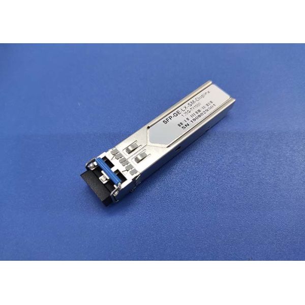
QSFP + 1310nm 40G LR4 SMF Fiber Optic Module LC Connector Single Mode 10KM
Applications
40G Ethernet
Infiniband interconnects
40G Telecom connections
Data Centers
PRODUCT FEATURES
1. Hot-pluggable QSFP+ form factor
2. Supports 41.2 Gb/s aggregate bit rates
3. Power dissipation < 3.5W
4. RoHS-6 compliant (lead-free)
5. Commercial temperature range 0°C to 70°C(Standard), -40°C to 85°C (Industrial)
6. Single 3.3V power supply
7. Maximum link length of 10km on Single Mode Fiber (SMF)
8. Uncooled 4x10Gb/s CWDM transmitter
9. XLPPI electrical interface
10. Duplex LC receptacles
11. Built-in digital diagnostic functions
PRODUCT DESCRIPTION
QSFP+ transceiver modules are designed for use in 40 Gigabit Ethernet links over single mode fiber. They are compliant with the QSFP+ MSA and IEEE 802.3ba 40GBASE-LR4. These transceivers are focused for use in controlled environments such as data centers. Digital diagnostics functions are available via an I2C interface, as specified by the QSFP+ MSA. The optical transceiver is compliant per the RoHS Directive 2011/65/EU.
Optical module also be called optical fiber module, the translation should be transceiver module. The function of the optical module is the photoelectric conversion, and the transmitter converts the electrical signal into the optical signal. After the transmission through the optical fiber, the receiving end converts the optical signal into the electrical signal. QSFP is a kind of optical module.
Optical fiber module classification: according to function:It includes optical receiving module, optical transmitting module, optical transceiver module and optical transmitting module
The 40GBASE QSFP+ (Quad Small Form-Factor Pluggable Plus) modules offer customers a wide variety of high-density 40 Gigabit Ethernet connectivity options for data center, high-performance computing networks, enterprise core and distribution layers, and service provider transport applications.
Parameter | Symbol | Min. | Typ. | Max. | Unit | Notes |
Maximum Supply Voltage | Vcc3 | -0.5 | - | 4.0 | V | |
Storage Temperature | TS | -40 | - | 85 | °C | |
Operating Humidity | - | 5 | - | 95 | % | |
Maximum Supply Voltage | Vcc3 | -0.5 | - | 4.0 | V |
Parameter | Symbol | Min. | Typ. | Max. | Unit | Notes |
Power Supply Voltage | Vcc | 3.13 | 3.30 | 3.47 | V | |
Power Supply Current | Icc | - | - | 300 | mA | |
Case Operating Temperature | Top | 0 | - | 70 | °C | |
Data Rate | - | - | 40 | - | Gb/s | |
9/125um G652 SMF | Lmax | - | - | 150 | m |
Optical Characteristics s (TOP = 0 to 70°C, VCC = 3.135 to 3.465 Volts):
Parameter | Symbol | Min. | Typical | Max. | Unit | Note |
Transmitter: | ||||||
Wavelength Assignment | λc | 1260 | 1310 | 1355 | nm | |
Spectral Width(RMS) | λrms | 3.5 | nm | |||
Side-mode Suppression Ratio | SMSR | 30 | dB | |||
Average Launch Power, each Lane | PAVG | -5.5 | 1.5 | dBm | ||
Optical Modulation Amplitude, each Lane | POMA | -4.5 | 2 | dBm | ||
Difference in Launch Power between any two Lanes (OMA) | 5 | dB | ||||
Laser Off Power Per Channel | Poff | -30 | dBm | |||
Optical Extinction Ratio | ER | 3.5 | dB | |||
Transmitter Eye Mask Definition {X1, X2, X3, Y1, Y2, Y3} | {0.25, 0.4, 0.45, 0.25, 0.28, 0.4} | |||||
Relative Intensity Noise | RIN | -128 | dB/Hz | 1 | ||
Optical Return Loss Tolerance | TOL | 12 | dB | |||
Transmitter Raflextance | RT | -12 | dB |
Note: 1. 12dB Reflection