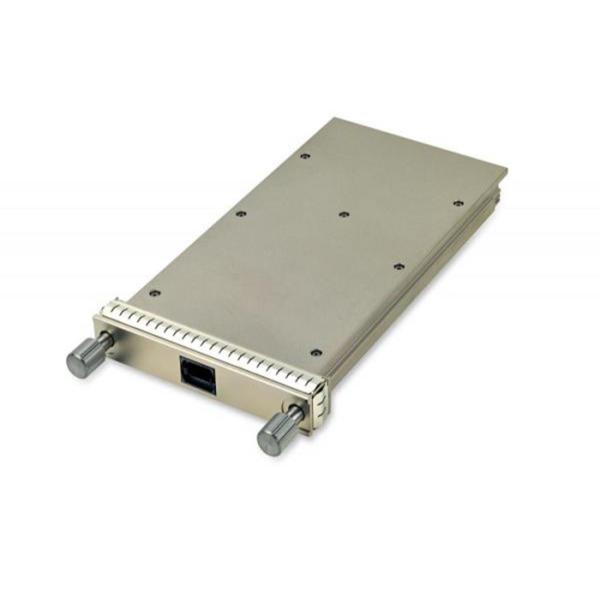
100GBASE-LR4 10km CFP Optical Module 1310nm Fibre Channel Transceiver
Applications
OTN OTU4 4I1-9D1F
100GBASE-LR4 100G Ethernet
PRODUCT FEATURES
Hot-pluggable CFP form factor
Supports 103.1Gb/s aggregate bit rate
Power dissipation < 24W
RoHS-6 compliant (lead-free)
Commercial case temperature range of 0°C to 70°C(Standard)/ -40°C to 85°C (Industrial)
Single 3.3V power supply
Maximum link length of 10km on Single Mode Fiber (SMF)
Temperature-stabilized 4x25Gb/s LAN-WDM transmitter
CAUI electrical interface
Duplex LC receptacles
MDIO management interface
PRODUCT DESCRIPTION
100G CFP LR4 is a optical transceiver module which is a hot pluggable form factor designed for high speed optical networking application. It is designed for 100 Gigabit Ethernet application and provides 100GBASE-LR4 compliant optical interface, CAUI electrical interface and MDIO module management interface.
100G-CFP-LR4 compliant with the CFP MSA1, IEEE 802.3ba 100GBASE-LR42 and OTU4 4I1-9D1F requirements specified in ITU-T Recommendations G.959.1/G.709 and Supplement 39 (G.sup39). Digital diagnostics functions are available via the MDIO interface. The transceiver is RoHS-6 compliant and lead-free.
100G-CFP-LR4 100GE CFP transceiver modules are designed for use in 100 Gigabit Ethernet links over single mode fiber. They are compliant with the CFP MSA and IEEE 802.3ba 100GBASE-LR4. Digital diagnostics functions are available via an MDIO interface, as specified by the CFP MSA. The transceiver is RoHS-6 compliant and lead-free per Directive 2002/95/EC.
Optical Transmitter Characteristics
Parameter | Symbol | Min | Typ. | Max | Unit | Notes |
Signaling rate, each lane | 25.78125 | GBd | ||||
Lane wavelength(range) | 1294.53 | 1295.56 | 1296.59 | nm | ||
1299.02 | 1300.05 | 1301.09 | nm | |||
1303.54 | 1304.58 | 1305.63 | nm | |||
1308.09 | 1309.14 | 1310.19 | nm | |||
Rate tolerance | -100 | 100 | ppm | From nominal rate | ||
Side-mode suppression ratio | SMSR | 30 | dB | |||
Total launch power | 10.5 | dBm | ||||
Average launch power, each lane | Pavg | -4.3 | 4.5 | dBm | ||
Extinction Ratio | ER | 4 | 8.2 | dB | ||
Optical modulation amplitude, each lane (OMA) | OMA | -1.3 | 4.5 | dBm | ||
Difference in launch power between any two lanes (OMA) | 5 | dB | ||||
Transmitter and Dispersion Penalty, each lane | TDP | 2.2 | dB | |||
OMA minus TDP, each lane | OMA-TDP | -2.3 | dBm | |||
Average launch power of OFF transmitter, each lane | -30 | dBm | ||||
Relative Intensity Noise | RIN20O MA | -130 | dB/Hz | |||
Transmitter reflectance | -12 | dB | ||||
Transmitter eye mask {X1, X2, X3, Y1, Y2, Y3} | {0.25, 0.4, 0.45, 0.25, 0.28, 0.4} |
Optical Receiver Characteristics
Parameter | Symbol | Min | Typ. | Max | Unit | Notes |
Signaling rate, each lane | 25.78125 | GBd | ||||
Rate tolerance | -100 | 100 | ppm | From normal rate | ||
Average receive power, each lane | Pavg | -10.6 | 4.5 | dBm | ||
Receive power, each lane (OMA) | 4.5 | dBm | ||||
Difference in receiver power between any two lanes (OMA) | 5.5 | dB | ||||
Receiver Sensitivity (OMA), each lane | Rsen | -8.6 | dBm | 1 | ||
Stressed Receiver Sensitivity (OMA), each lane | SRS | -6.8 | dBm | |||
Stressed receiver sensitivity test conditions | ||||||
Vertical eye closure penalty, each lane | VECP | 1.8 | dB | |||
Stressed sys J2 jitter, each lane | J2 | 0.3 | UI | 2 | ||
Stressed sys J9 jitter, each lane | J9 | 0.47 | UI | 2 | ||
Receiver reflectance | -26 | dB | ||||
LOS Assert | Plos_on | -18 | dBm | |||
LOS Deassert | Plos_off | -15 | dBm | |||
LOS Hysteresis | 0.5 | dB | ||||
|