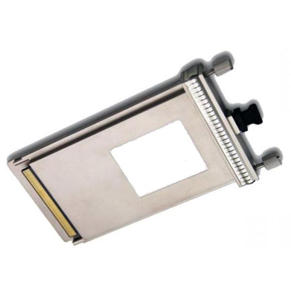
40GBASE-ER4 40km CFP Optical Module 1550nm Single Mode Dual LC For Data Center
Applications
Metro Network
Switch and Router
40G Ethernet Client Side
Rack to Rack
Data Center
Premise
PRODUCT FEATURES
Supports 41.2Gbps aggregate bit rates
DFB laser and PIN receiver
Up to 40km transmission on SMF
Single 3.3V Power Supply and Power dissipation <8W
Hot-Pluggable CFP Footprint Duplex LC Connector Interface
Class 1 FDA and IEC60825-1 Laser Safety Compliant
Operating Case Temperature Standard: 0C~+70C
Compliant with CFP MSA Specification
MDIO interface with integrated Digital Diagnostic Monitoring
XLAUI electrical interface
PRODUCT DESCRIPTION
40GBASE-ER4 CFP module are a high performance, low power consumption, extended reach(40km) , links over single mode fiber interconnect solution supporting 40G Ethernet and PCIe. It is compliant with the CFP MSA and IEEE P802.3ba 40GBASE-ER4. CFP ER4 modules offer 4 transmit and 4 receive asynchronous channels operating at up to 11.2Gbps per channel.
The transmitter side of the module consists of an array of VCSELs (Vertical Cavity Surface Emitting Lasers) and associated circuitry, which converts 4 parallel electrical data inputs to 4 parallel optical data output signals and also converts 4 parallel optical signals into 4 parallel electrical signals through an array of PIN photodiodes and associated circuitry.
Digital diagnostics functions are available via an MDIO interface, as specified by the CFP MSA. The transceiver is RoHS-6 compliant and lead-free per Directive 2002/95/EC3.
Optical Transmitter Characteristics
Parameter | Symbol | Min | Typ. | Max | Unit | Notes |
Signaling rate, each lane | 10.3125 | GBd | ||||
Rate tolerance | -100 | 100 | ppm | From nominal rate | ||
Side-mode suppression ratio | SMSR | 30 | dB | |||
Total launch power | 10.5 | dBm | ||||
Average launch power, each lane | Pavg | -4.3 | 4.5 | dBm | ||
Extinction Ratio | ER | 4 | 8.2 | dB | ||
Optical modulation amplitude, each lane (OMA) | OMA | -1.3 | 4.5 | dBm | ||
Difference in launch power between any two lanes (OMA) | 5 | dB | ||||
Transmitter and Dispersion Penalty, each lane | TDP | 2.2 | dB | |||
OMA minus TDP, each lane | OMA-TDP | -2.3 | dBm | |||
Average launch power of OFF transmitter, each lane | -30 | dBm | ||||
Relative Intensity Noise | RIN20O MA | -130 | dB/Hz | |||
Transmitter reflectance | -12 | dB | ||||
Transmitter eye mask {X1, X2, X3, Y1, Y2, Y3} | {0.25, 0.4, 0.45, 0.25, 0.28, 0.4} |
Optical Receiver Characteristics
Parameter | Symbol | Min | Typ. | Max | Unit | Notes |
Signaling rate, each lane | 10.3125 | GBd | ||||
Rate tolerance | -100 | 100 | ppm | From normal rate | ||
Average receive power, each lane | Pavg | -10.6 | 4.5 | dBm | ||
Receive power, each lane (OMA) | 4.5 | dBm | ||||
Difference in receiver power between any two lanes (OMA) | 5.5 | dB | ||||
Receiver Sensitivity (OMA), each lane | Rsen | -8.6 | dBm | 1 | ||
Stressed Receiver Sensitivity (OMA), each lane | SRS | -6.8 | dBm | |||
Stressed receiver sensitivity test conditions | ||||||
Vertical eye closure penalty, each lane | VECP | 1.8 | dB | |||
Stressed sys J2 jitter, each lane | J2 | 0.3 | UI | 2 | ||
Stressed sys J9 jitter, each lane | J9 | 0.47 | UI | 2 | ||
Receiver reflectance | -26 | dB | ||||
LOS Assert | Plos_on | -18 | dBm | |||
LOS Deassert | Plos_off | -15 | dBm | |||
LOS Hysteresis | 0.5 | dB | ||||
|