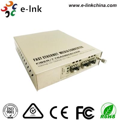
10Gb/s XFP CWDM Duplex LC 1470~1610nm SFP Optical Transceiver Module
Features:
Applications:
Description:
E-link’ LNK-XFP-10G-CWDM Small Form Factor 10Gb/s (XFP) transceivers are compliant with the current XFP Multi-Source Agreement (MSA) Specification. The high performance cooled CWDM EML transmitter and high sensitivity PIN receiver provide superior performance for SONET/SDH and Ethernet applications up to 40km optical links.
l Absolute Maximum Ratings
Parameter | Symbol | Min | Max | Unit |
Storage Temperature | TST | -40 | +85 | ℃ |
Case Operating Temperature | TIP | 0 | +70 | ℃ |
Supply Voltage 1 | VCC3 | -0.5 | +4.0 | V |
Supply Voltage 2 | VCC5 | -0.5 | +6.0 | V |
l Electrical Characteristics (Condition: TOP = 0 to 70 °C)
Parameter | Symbol | Min | Typ | Max | Unit | Note |
Supply Voltage 1 | Vcc5 | 4.75 | 5.25 | V | ||
Supply Voltage 2 | Vcc3 | 3.13 | 3.45 | V | ||
Supply Current – Vcc5 supply | Icc5 | 250 | mA | |||
Supply Current – Vcc3 supply | Icc3 | 500 | mA | |||
Module total power | P | 3.5 | W | |||
Transmitter | ||||||
Input differential impedance | Rin | 100 | Ω | 1 | ||
Differential data input swing | Vin,pp | 150 | 820 | mV |
Transmit Disable Voltage | VD | 2.0 | Vcc | V | ||
Transmit Enable Voltage | VEN | GND | GND+0.8 | V | ||
Transmit Disable Assert Time | T_off | 100 | ms | |||
Tx Enable Assert Time | T_on | 100 | ms | |||
Receiver | ||||||
Differential data output swing | Vout,pp | 300 | 500 | 850 | mV | |
Data output rise time | tr | 35 | ps | 2 | ||
Data output fall time | tf | 35 | ps | 2 | ||
LOS Fault | VLOS fault | Vcc – | VccHOST | V | 3 | |
0.5 | ||||||
LOS Normal | VLOS norm | GND | GND+0.5 | V | 3 | |
Power Supply Rejection | PSR | See Note 4 below | 4 |
Note:
l Optical Characteristics (Condition: TOP = 0 to 70°C)
Parameter | Symbol | Min | Typ | Max | Unit | Ref. | ||
Transmitter | ||||||||
Operating Date Rate | B | 9.95 | 11.3 | Gb/s | ||||
Bit Error Rate | BER | 10-12 | ||||||
Output Power | Po | -1 | +4 | dBm | 1 | |||
Optical Wavelength | λ | λ-6.5 | λ+6.5 | nm | ||||
Optical Extinction Ratio | ER | 6 | dB | |||||
Spectral Width | Δλ | 1 | nm | |||||
Side mode Suppression ratio | SMSRmin | 30 | dB | |||||
Rise/Fall Time (20%~80%) | Tr/Tf | 35 | ps | |||||
Average Launch power of OFF | POFF | -30 | dBm | |||||
Transmitter | ||||||||
Tx Jitter | Txj | Compliant with each standard | ||||||
requirements | ||||||||
Optical Eye Mask | IEEE802.3ae | 2 | ||||||
Receiver | ||||||||
Operating Date Rate | BR | 9.95 | 11.3 | Gb/s | ||||
Receiver Sensitivity | Sen | -16 | dBm | 2 | ||||
Maximum Input Power | PMAX | 0 | dBm | 2 | ||||
Optical Center Wavelength | λC | 1260 | 1600 | nm | ||||
Receiver Reflectance | Rrx | -27 | dB | |||||
LOS De-Assert | LOSD | -17 | dBm | |||||
LOS Assert | LOSA | -27 | dBm | |||||
LOS Hysteresis | LOSH | 0.5 | 5 | dB | ||||
Notes: |
Pin Assignment:
Diagram of Host Board Connector Block Pin Numbers and Name
Pin Description:
Pin | Logic | Symbol | Name/Description | Ref. | |
1 | GND | Module Ground | 1 | ||
2 | VEE5 | Optional –5.2 Power Supply – Not required | |||
3 | LVTTL-I | Mod-Desel | Module De-select; When held low allows the module to , | ||
respond to 2-wire serial interface commands | |||||
4 | LVTTL-O | Interrupt (bar); Indicates presence of an important condition | 2 | ||
Interrupt | which can be read over the serial 2-wire interface | ||||
5 | LVTTL-I | TX_DIS | Transmitter Disable; Transmitter laser source turned off | ||
6 | VCC5 | +5 Power Supply | |||
7 | GND | Module Ground | 1 | ||
8 | VCC3 | +3.3V Power Supply | |||
9 | VCC3 | +3.3V Power Supply | |||
10 | LVTTL-I | SCL | Serial 2-wire interface clock | 2 | |
11 | LVTTL- | SDA | Serial 2-wire interface data line | 2 | |
I/O | |||||
12 | LVTTL-O | Mod_Abs | Module Absent; Indicates module is not present. Grounded in | 2 | |
the module. | |||||
13 | LVTTL-O | Mod_NR | Module Not Ready; | 2 | |
14 | LVTTL-O | RX_LOS | Receiver Loss of Signal indicator | 2 | |
15 | GND | Module Ground | 1 | ||
16 | GND | Module Ground | 1 |
17 | CML-O | RD- | Receiver inverted data output | ||
18 | CML-O | RD+ | Receiver non-inverted data output | ||
19 | GND | Module Ground | 1 | ||
20 | VCC2 | +1.8V Power Supply – Not required | |||
Power Down; When high, places the module in the low power | |||||
stand-by mode and on the falling edge of P_Down initiates a | |||||
21 | LVTTL-I | P_Down/RST | module reset | ||
Reset; The falling edge initiates a complete reset of the | |||||
module including the 2-wire serial interface, equivalent to a | |||||
power cycle. | |||||
22 | VCC2 | +1.8V Power Supply – Not required | |||
23 | GND | Module Ground | 1 | ||
24 | PECL-I | RefCLK+ | Reference Clock non-inverted input, AC coupled on the host | 3 | |
board – Not required | |||||
25 | PECL-I | RefCLK- | Reference Clock inverted input, AC coupled on the host board | 3 | |
– Not required | |||||
26 | GND | Module Ground | 1 | ||
27 | GND | Module Ground | 1 | ||
28 | CML-I | TD- | Transmitter inverted data input | ||
29 | CML-I | TD+ | Transmitter non-inverted data input | ||
30 | GND | Module Ground | 1 |
Note
Digital Diagnostic Functions:
As defined by the XFP MSA 1 , E-link’s XFP transceivers provide digital diagnostic functions via a 2-wire serial interface, which allows real-time access to the following operating parameters:
It also provides a sophisticated system of alarm and warning flags, which may be used to alert end-users when particular operating parameters are outside of a factory-set normal range.
The operating and diagnostics information is monitored and reported by a Digital Diagnostics Transceiver Controller (DDTC) inside the transceiver, which is accessed through the 2-wire serial interface. When the serial protocol is activated, the serial clock signal (SCL pin) is generated by the host. The positive edge clocks data into the XFP transceiver into those segments of its memory map that are not write-protected. The negative edge clocks data from the XFP transceiver. The serial data signal (SDA pin) is bi-directional for serial data transfer. The host uses SDA in conjunction with SCL to mark the start and end of serial protocol activation. The memories are organized as a series of 8-bit data words that can be addressed individually or sequentially. The 2-wire serial interface provides sequential or random access to the 8 bit parameters, addressed from 000h to the maximum address of the memory.