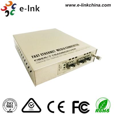
Fiber Optic Module 40G QSFP Transceiver Single Mode Duplex LC Connector 2KM
40G QSFP+ Transceiver Advantages
► 4 independent full-duplex channels
► TX input and RX output CDR retiming
► CML compatible electrical I/O
► MTP/MPO optical connector
► Built-in digital diagnostic functions
Electrical Characteristics (TOP = 0 to 70 °C, VCC = 3.13 to 3.47 Volts)
Parameter | Symbol | Min | Typ | Max | Unit | Note |
Data Rate per Channel |
| - | 10.3125 | 11.2 | Gbps |
|
Power Consumption |
| - | 2.5 | 3.5 | W |
|
Supply Current | Icc |
| 0.75 | 1.0 | A |
|
Control I/O Voltage-High | VIH | 2.0 |
| Vcc | V |
|
Control I/O Voltage-Low | VIL | 0 |
| 0.7 | V |
|
Inter-Channel Skew | TSK |
|
| 150 | Ps |
|
RESETL Duration |
|
| 10 |
| Us |
|
RESETL De-assert time |
|
|
| 100 | ms |
|
Power On Time |
|
|
| 100 | ms |
|
Transmitter | ||||||
Single Ended Output Voltage Tolerance |
| 0.3 |
| 4 | V | 1 |
Common mode Voltage Tolerance |
| 15 |
|
| mV |
|
Transmit Input Diff Voltage | VI | 150 |
| 1200 | mV |
|
Transmit Input Diff Impedance | ZIN | 85 | 100 | 115 |
|
|
Data Dependent Input Jitter | DDJ |
| 0.3 |
| UI |
|
Receiver | ||||||
Single Ended Output Voltage Tolerance |
| 0.3 |
| 4 | V |
|
Rx Output Diff Voltage | Vo | 370 | 600 | 950 | mV |
|
Rx Output Rise and Fall Voltage | Tr/Tf |
|
| 35 | ps | 1 |
Total Jitter | TJ |
| 0.3 |
| UI |
Overview
The central wavelengths of the 4 CWDM channels are 1271, 1291, 1311 and 1331nm as members of the CWDM wavelength grid defined in ITU-T G694.2. It contains a duplex LC connector for the optical interface and a 38-pin connector for the electrical interface. To minimize the optical dispersion in the long-haul system, single-mode fiber (SMF) has to be applied in this module.
Diagnostic Monitoring Interface
Digital diagnostics monitoring function is available on all QSFP+ LR4. A 2-wire serial interface provides user to contact with module. The structure of the memory is shown in flowing. The memory space is arranged into a lower, single page, address space of 128 bytes and multiple upper address space pages. This structure permits timely access to addresses in the lower page, such as Interrupt Flags and Monitors. Less time critical time entries, such as serial ID information and threshold settings, are available with the Page Select function. The interface address used is A0xh and is mainly used for time critical data like interrupt handling in order to enable a one-time-read for all data related to an interrupt situation. After an interrupt, IntL has been asserted, the host can read out the flag field to determine the affected channel and type of flag.
Transceiver Block Diagram
Pin Assignment
Ordering Information
Part Number | Description |
LNK-QSFP-IR4 | 40G QSFP+ 1310nm 2KM IR4 LC |