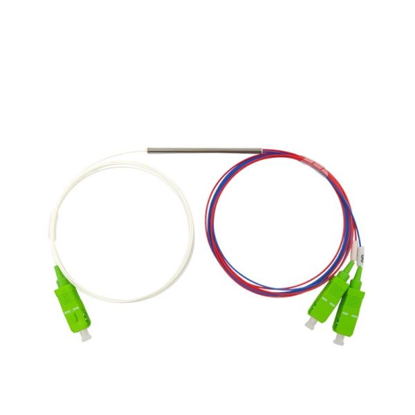
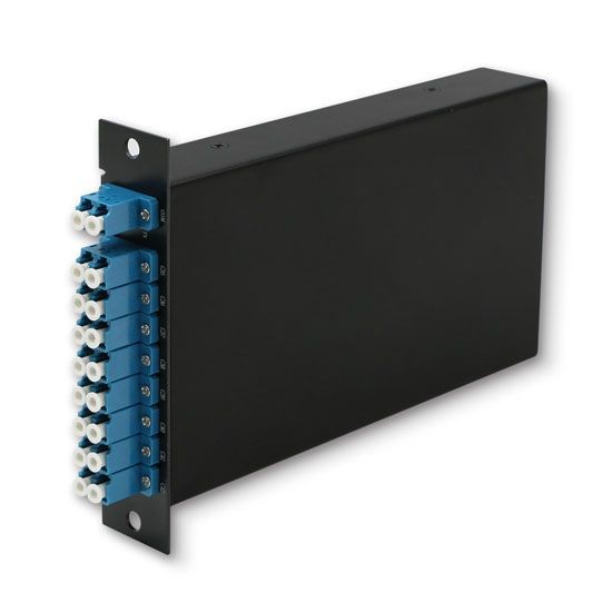
150GHz 17 channel O-band Gaussian Athermal AWG DWDM module
Athermal AWG (Arrayed Waveguide Grating) is a high performance DWDM mux/demux device operating on 150GHz channel spacing without the need for temperature stabilization. The planar processed silica-on-silicon chips comprise arrayed channel waveguides to separate or combine multiple wavelengths. Athermal AWG s allow multiplexing and demultiplexing of DWDM signals over a wide operating temperature range, without the need for heater drive and monitoring electronics. These AWGs offer low insertion loss, excellent channel isolation, ease of fiber handling, and long-term reliability in a compact package. Hangalaxy’s athermalization technology simplifies deployment of AWG multiplexers/demultiplexers by DWDM network providers.
Features
Low Insertion Loss
Wide pass band
High Channel Isolation
High Stability and reliability
Applications
WDM Network
Telecommunication
Access Network
Optical Specifications
Parameter | Specification | Units | Notes | |||
Min | Type | Max | ||||
Channel Spacing | 150 | Ghz | ||||
Number of Channel | 17 | Channels | ||||
Channel Frequencies | ITU Grid | THz | ||||
Available Channel Frequency Range | 233.60 | 231.2 | THz | |||
Channel Passband | -18.75 | +18.55 | Ghz | |||
-0.10 | +0.10 | nm | ||||
Center Wavelength Accuracy | -0.05 | +0.05 | nm | |||
Insertion Loss | COM-AWG | 2.0 | 2.5 | dB | @Center Wavelength | |
2.8 | 3.0 | dB | Full Bandwidth | |||
Bandwidth @1.0dB | 0.23 | nm | ||||
Bandwidth @3.0dB | 0.42 | nm | ||||
Bandwidth @20dB | 1.20 | nm | ||||
Insertion Loss Uniformity at ITU | 1.20 | dB | ||||
Polarization Dependent Loss | 0.5 | dB | ||||
Adjacent Channel Isolation | 27 | 30 | dB | |||
Non-Adjacent Channel Isolation | 30 | 35 | dB | |||
Total Cross Talk | 24 | 26 | dB | |||
Directivity | 45 | dB | ||||
Return Loss with connectors | 40 | 45 | dB | |||
Chromatic Dispersion | -20 | +20 | ps/nm | |||
PMD | 0.5 | ps | ||||
Optical Power Handling of Common Port | 25 | dBm |
Channel Plan 17 Port AWG - On grid
The AWG operate in O-band. The channels are as follows:
Channel | Frequency | Wavelength | Channel | Frequency | Wavelength |
No. | THz | nm | No. | THz | nm |
1 | 233.60 | 1283.358 | 10 | 232.25 | 1290.818 |
2 | 233.45 | 1284.183 | 11 | 232.10 | 1291.652 |
3 | 233.30 | 1285.008 | 12 | 231.95 | 1292.487 |
4 | 233.15 | 1285.835 | 13 | 231.80 | 1293.324 |
5 | 233.00 | 1286.663 | 14 | 231.65 | 1294.161 |
6 | 232.85 | 1287.492 | 15 | 231.50 | 1295.000 |
7 | 232.70 | 1288.322 | 16 | 231.35 | 1295.839 |
8 | 232.55 | 1289.153 | 17 | 231.20 | 1296.680 |
9 | 232.40 | 1289.985 | 18 |
Physical Parameters
Parameter | Min | Type | Max | Units |
Length | 100 | mm | ||
Width | 80 | mm | ||
Height | 9 | mm | ||
Length of Input fiber | 900 | mm | ||
Length of Output Fibers | 1000 | mm | ||
Number of Input Fiber | 1 | |||
Number of Output Fibers | 17 |