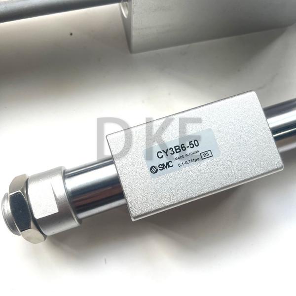
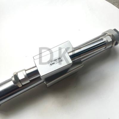
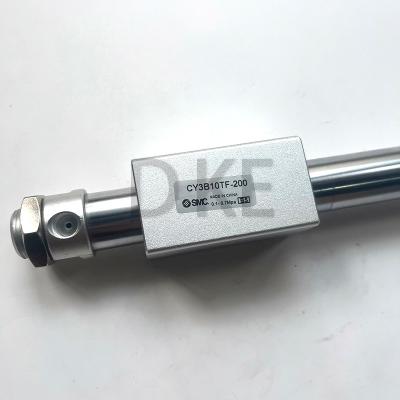
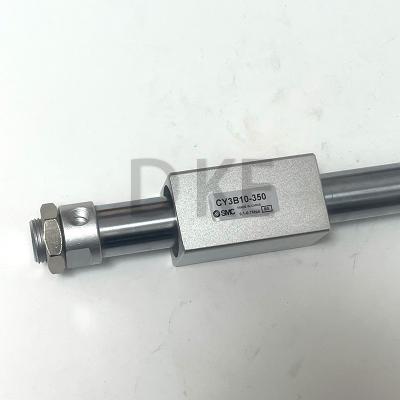
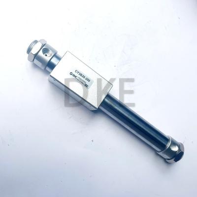
SMC Magnetically Coupled Rodless Pneumatic Cylinder CY3B6-50
SMC Magnetically Coupled Rodless Pneumatic Cylinder CY3B6-50 Precision High-Strength Piston Rod
The SMC rod less cylinder has magnetically coupled uses industrial strength magnets located in the piston and external carriage to form a single unit that will travel when actuated with air pressure.The product weight has been reduced through re-designing of the body and head cover shapes and employment of magnetic coupling.
Specifications
Attribute | Value |
Stroke | 50mm |
Bore | 6mm |
Manufacturer Series | CY3B |
Action | Double |
Maximum Operating Pressure | 7 bar |

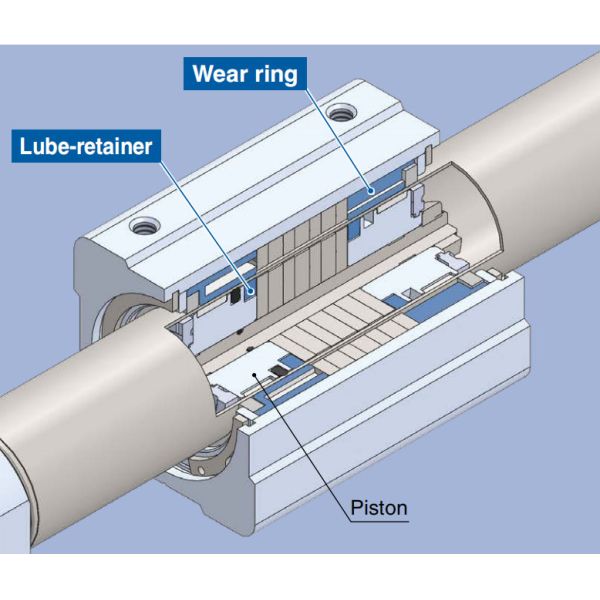
Improved lubrication
A Lube-retainer is installed to support lubrication retention on the piston and to ensure a lubrication film. (Bore size: ø15 to ø63)
Stable operation
Lengthening of the wear ring on the body side by, 30% at maximum, helps to achieve smooth movement.
MThe specifications, magnet holding force, and mounting dimensions are the same as those of the existing CY3B series model.
Max. Weight of Connection Bracket to the Body
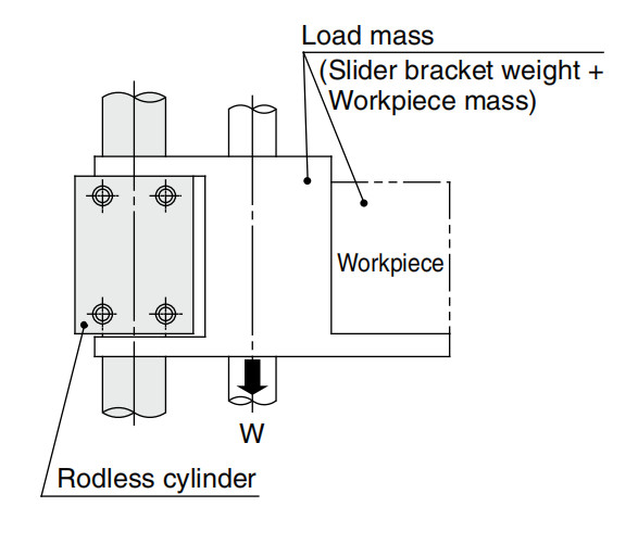
The CY3B series is guided by an external axis (such as a linear guide) without directly mounting the load. When designing a metal bracket to connect the load, make sure that its weight will not exceed the value in the table on the right. (For connection methods, refer to the Operation Manual.)
- Max. Connection Bracket Weight
Model | Max. connection bracket weight (Wemax) [kg] |
CY3B6 | 0.2 |
CY3B6 | 0.4 |
CY3B15 | 1 |
CY3B20 | 1.1 |
CY3B25 | 1.2 |
CY3B32 | 1.5 |
CY3B40 | 2 |
CY3B50 | 2.5 |
CY3B63 | 3 |
Vertical Operation
It is recommended that the load is guided by a ball type bearing (linear guide, etc.). If a slide bearing is used, sliding resistance increases due to the load mass and moment, which may cause malfunctions. When the cylinder is mounted vertically or on an angle, be sure to use an external stopper, etc., for positioning. In addition, as the slider may move downward toward the stroke end due to its self-weight or the mass of the workpiece, use an external stopper, etc., for positioning if accurate positioning is required.
Bore size [mm] | Model | Allowable load mass (Wv) [kg] | Max. operating pressure (Pv) [MPa] |
6 | CY3B6 | 1 | 0.55 |
10 | CY3B10 | 2.7 | 0.55 |
15 | CY3B15 | 7 | 0.65 |
20 | CY3B20 | 11 | 0.65 |
25 | CY3B25 | 18.5 | 0.65 |
32 | CY3B32 | 30 | 0.65 |
40 | CY3B40 | 47 | 0.65 |
50 | CY3B50 | 75 | 0.65 |
63 | CY3B63 | 115 | 0.65 |
∗ Use caution, as there is a danger of breaking the magnetic coupling if operated above the max. operating pressure.