Stock Offer (Hot Sell)
Part no. | Quantity | Brand | D/C | Package |
OP484F | 2000 | AD | 15+ | SOP-14 |
P6KE13CA | 2000 | VISHAY | 16+ | DO-15 |
SJA1000T | 2000 | 16+ | SOP28 | |
SN74AHC245PWR | 2000 | TI | 14+ | TSSOP |
SN74HC14N | 2000 | TI | 14+ | DIP |
SN74HC273PWR | 2000 | TI | 14+ | TSSOP |
SS32 A | 2000 | VISHAY | 16+ | DO-214AC |
STF11NM60N | 2000 | ST | 16+ | TO-220F |
SY100EP11UKG | 2000 | MICREL | 13+ | MSOP-8 |
TAS5342ADDVR | 2000 | TI | 15+ | HTSSOP-44 |
TDA7050T | 2000 | 16+ | SOP8 | |
TJA1040T | 2000 | 16+ | SOP-8 | |
TPS54332DDAR | 2000 | TI | 14+ | SOP8 |
HEF4051 | 2005 | 14+ | SOP-16 | |
ZTX951 | 2005 | ZETEX | 14+ | TO-92 |
UC3879N | 2008 | TI | 16+ | DIP |
LM2576HVT-ADJ | 2010 | NS | 16+ | TO220 |
SN74HC02N | 2010 | TI | 13+ | DIP |
AT93C46DN-SH-T | 2027 | ATMEL | 15+ | SOP8 |
40CPQ100PBF | 2055 | VISHAY | 16+ | TO-247 |
LPC1752FBD80 | 2080 | 16+ | LQFP80 | |
PIC16F1934-I/PT | 2080 | MICROCHIP | 14+ | QFP |
1N5362B | 2100 | ON | 14+ | DIP |
6N137SD | 2100 | FSC | 14+ | SOP8 |
CD4047BM96 | 2100 | TI | 16+ | SOP |
FSDL0165RN | 2100 | FSC | 16+ | DIP-8 |
ISD17240PY | 2100 | ISD | 13+ | DIP28 |
MC34063 | 2100 | ON | 15+ | SOP8 |
MDP13N50TH | 2100 | MAGNACHIP | 16+ | TO-220 |
PIC16F72-I/SP | 2100 | MICROCHIP | 16+ | DIP-28 |
Product Description
AT91SAM7X512 AT91SAM7X256 AT91SAM7X128
Features
• Incorporates the ARM7TDMI® ARM® Thumb® Processor
– High-performance 32-bit RISC Architecture
– High-density 16-bit Instruction Set
• Leader in MIPS/Watt
– EmbeddedICE™ In-circuit Emulation, Debug Communication Channel Support
• Internal High-speed Flash
– 512 Kbytes (AT91SAM7X512) Organized in Two Banks of 1024 Pages of 256 Bytes (Dual Plane)
– 256 Kbytes (AT91SAM7X256) Organized in 1024 Pages of 256 Bytes (Single Plane)
– 128 Kbytes (AT91SAM7X128) Organized in 512 Pages of 256 Bytes (Single Plane)
• Single Cycle Access at Up to 30 MHz in Worst Case Conditions
• Prefetch Buffer Optimizing Thumb Instruction Execution at Maximum Speed
• Page Programming Time: 6 ms, Including Page Auto-erase, Full Erase Time: 15 ms
• 10,000 Write Cycles, 10-year Data Retention Capability, Sector Lock Capabilities, Flash Security Bit
• Fast Flash Programming Interface for High Volume Production
• Internal High-speed SRAM, Single-cycle Access at Maximum Speed
– 128 Kbytes (AT91SAM7X512)
– 64 Kbytes (AT91SAM7X256)
– 32 Kbytes (AT91SAM7X128)
• Memory Controller (MC)
– Embedded Flash Controller, Abort Status and Misalignment Detection
• Reset Controller (RSTC)
– Based on Power-on Reset Cells and Low-power Factory-calibrated Brownout Detector
– Provides External Reset Signal Shaping and Reset Source Status
• Clock Generator (CKGR)
– Low-power RC Oscillator, 3 to 20 MHz On-chip Oscillator and one PLL
• Power Management Controller (PMC)
– Power Optimization Capabilities, Including Slow Clock Mode (Down to 500 Hz) and Idle Mode
– Four Programmable External Clock Signals
• Advanced Interrupt Controller (AIC)
– Individually Maskable, Eight-level Priority, Vectored Interrupt Sources
– Two External Interrupt Sources and One Fast Interrupt Source, Spurious Interrupt Protected
• Debug Unit (DBGU)
– 2-wire UART and Support for Debug Communication Channel interrupt,
Programmable ICE Access Prevention
• Periodic Interval Timer (PIT)
– 20-bit Programmable Counter plus 12-bit Interval Counter
• Windowed Watchdog (WDT)
– 12-bit key-protected Programmable Counter
– Provides Reset or Interrupt Signals to the System
– Counter May Be Stopped While the Processor is in Debug State or in Idle Mode
• Real-time Timer (RTT)
– 32-bit Free-running Counter with Alarm
– Runs Off the Internal RC Oscillator
• Two Parallel Input/Output Controllers (PIO)
– Sixty-two Programmable I/O Lines Multiplexed with up to Two Peripheral I/Os
– Input Change Interrupt Capability on Each I/O Line
– Individually Programmable Open-drain, Pull-up Resistor and Synchronous Output
• Thirteen Peripheral DMA Controller (PDC) Channels
• One USB 2.0 Full Speed (12 Mbits per second) Device Port
– On-chip Transceiver, 1352-byte Configurable Integrated FIFOs
• One Ethernet MAC 10/100 base-T
– Media Independent Interface (MII) or Reduced Media Independent Interface (RMII)
– Integrated 28-byte FIFOs and Dedicated DMA Channels for Transmit and Receive
• One Part 2.0A and Part 2.0B Compliant CAN Controller
– Eight Fully-programmable Message Object Mailboxes, 16-bit Time Stamp Counter
• One Synchronous Serial Controller (SSC)
– Independent Clock and Frame Sync Signals for Each Receiver and Transmitter
– I²S Analog Interface Support, Time Division Multiplex Support
– High-speed Continuous Data Stream Capabilities with 32-bit Data Transfer
• Two Universal Synchronous/Asynchronous Receiver Transmitters (USART)
– Individual Baud Rate Generator, IrDA® Infrared Modulation/Demodulation
– Support for ISO7816 T0/T1 Smart Card, Hardware Handshaking, RS485 Support
– Full Modem Line Support on USART1
• Two Master/Slave Serial Peripheral Interfaces (SPI)
– 8- to 16-bit Programmable Data LeCM GROUPh, Four External Peripheral Chip Selects
• One Three-channel 16-bit Timer/Counter (TC)
– Three External Clock Inputs, Two Multi-purpose I/O Pins per Channel
– Double PWM Generation, Capture/Waveform Mode, Up/Down Capability
• One Four-channel 16-bit Power Width Modulation Controller (PWMC)
• One Two-wire Interface (TWI)
– Master Mode Support Only, All Two-wire Atmel EEPROMs and I2 C Compatible Devices Supported
• One 8-channel 10-bit Analog-to-Digital Converter, Four Channels Multiplexed with Digital I/Os
• SAM-BA™ Boot Assistance
– Default Boot program
– Interface with SAM-BA Graphic User Interface
• IEEE® 1149.1 JTAG Boundary Scan on All Digital Pins
• 5V-tolerant I/Os, Including Four High-current Drive I/O lines, Up to 16 mA Each
• Power Supplies
– Embedded 1.8V Regulator, Drawing up to 100 mA for the Core and External Components
– 3.3V VDDIO I/O Lines Power Supply, Independent 3.3V VDDFLASH Flash Power Supply
– 1.8V VDDCORE Core Power Supply with Brownout Detector
• Fully Static Operation: Up to 55 MHz at 1.65V and 85°C Worst Case Conditions
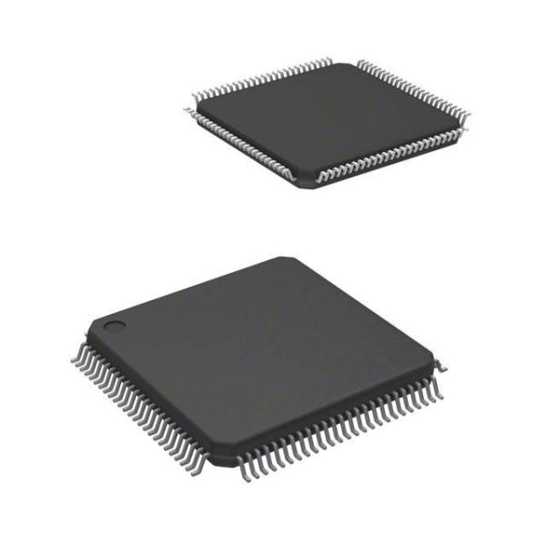
• Available in 100-lead LQFP Green and 100-ball TFBGA Green Packages
AT91SAM7X512/256/128 Block Diagram