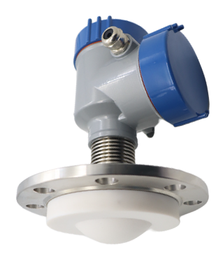
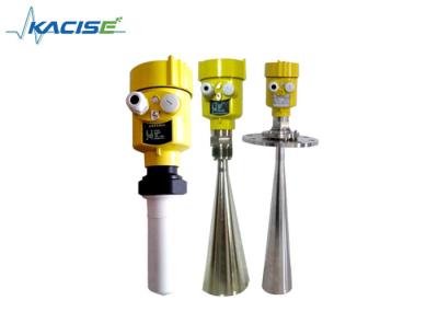
KLD805 80G FM Radar Level Sensor
Introduction
Communication and commissioning
The instrument can be debugged through LCD on site, and the optional upper computer software can also be debugged on the PC. The communication between the instrument and PC is carried out through the following ways:
1. USB to RS485 serial port cable (four-wire system);
2. USB to TTL serial port cable (two-wire system);
3. USB to Hart-modem (two-wire system) for communication.
4. Through the Bluetooth debugging of mobile phones, the on-site debugging is safer and more convenient.
5. 4G network, remote debugging through remote module.
Feature
·Based on the self-developed CMOS millimeter wave RF chip, it can achieve a more compact RF architecture, higher signal-to-noise ratio and smaller blind area.
5GHz working bandwidth enables the product to have higher measurement resolution and measurement accuracy.
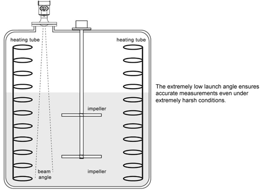
·The narrowest 3 ° antenna beam angle, the interference in the installation environment has less impact on the instrument, and the installation is more convenient.
With shorter wavelength and better reflection characteristics on the solid surface, it is not necessary to use universal flange for aiming.
Support remote debugging and remote upgrade, reduce waiting time and improve work efficiency.
·Support Bluetooth debugging of mobile phones, convenient for on-site maintenance
KLD805 | Medium: strong corrosive liquid, steam, foam, high temperature. and high pressure Measuring range: 0.1m~10/20/30/60/100m Process connection: flange ≥ DN80 Process temperature: -40~200℃ Process pressure: -0.1~2.5MPa Antenna size: 76mm lens antenna (according to flange size) Antenna material: PTFE/overall filling Accuracy: ±1mm Protection class: IP67 Center frequency: 80GHz Launch angle: 3° Power supply: two-wire /DC24V four-wire /DC12~24V four-wire /AC220V Casing: aluminum / plastic / stainless steel Signal output: two-wire /4...20mA/HART protocol four-wire 4...20mA/ RS485 Modbus |
Installation
Installation Requirements
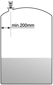
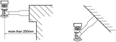
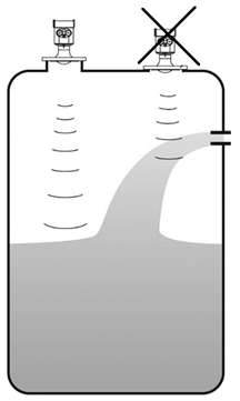
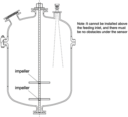
When installing the instrument, avoid installing it above the material inlet, and try to avoid various objects that affect the signal, such as stirring paddles, etc.
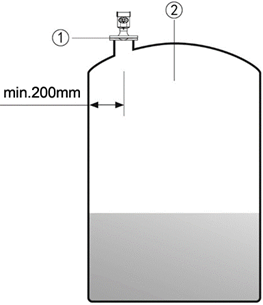
Under extremely complex working conditions, the instrument can work normally if there is no obstacle in the area with a radius of 20cm centered on the installation point.
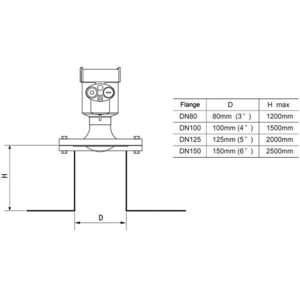
Installation connection diagram:
The maximum installation spool height H max depends on the installation spool diameter D and the size of the product launch angle.
Too long installation connection will affect the radar performance.
Dimensions
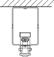
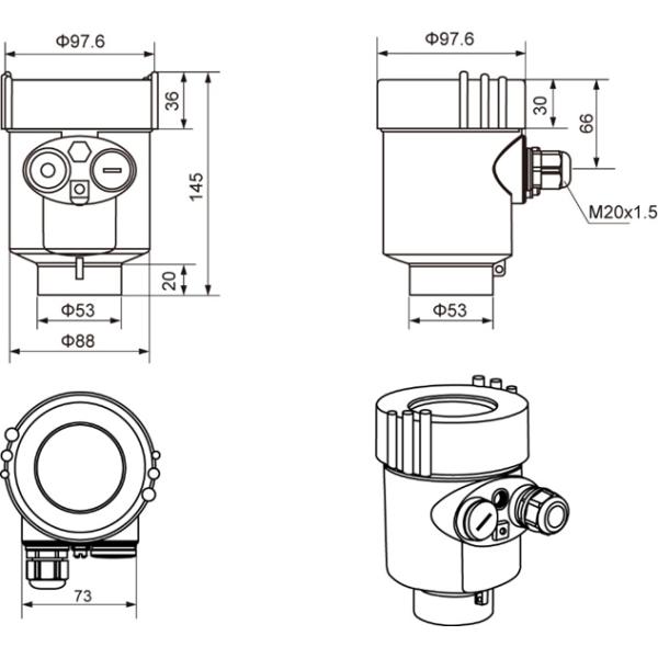
Casing Dimension
Unit in mm:
Production:
Xi'an Kacise Optronics Tech Co., Ltd considers itself a solution provider and manufacturer. We offer maximum flexibility and a cost-optimised offer for our OEM customers.
What we could provide:
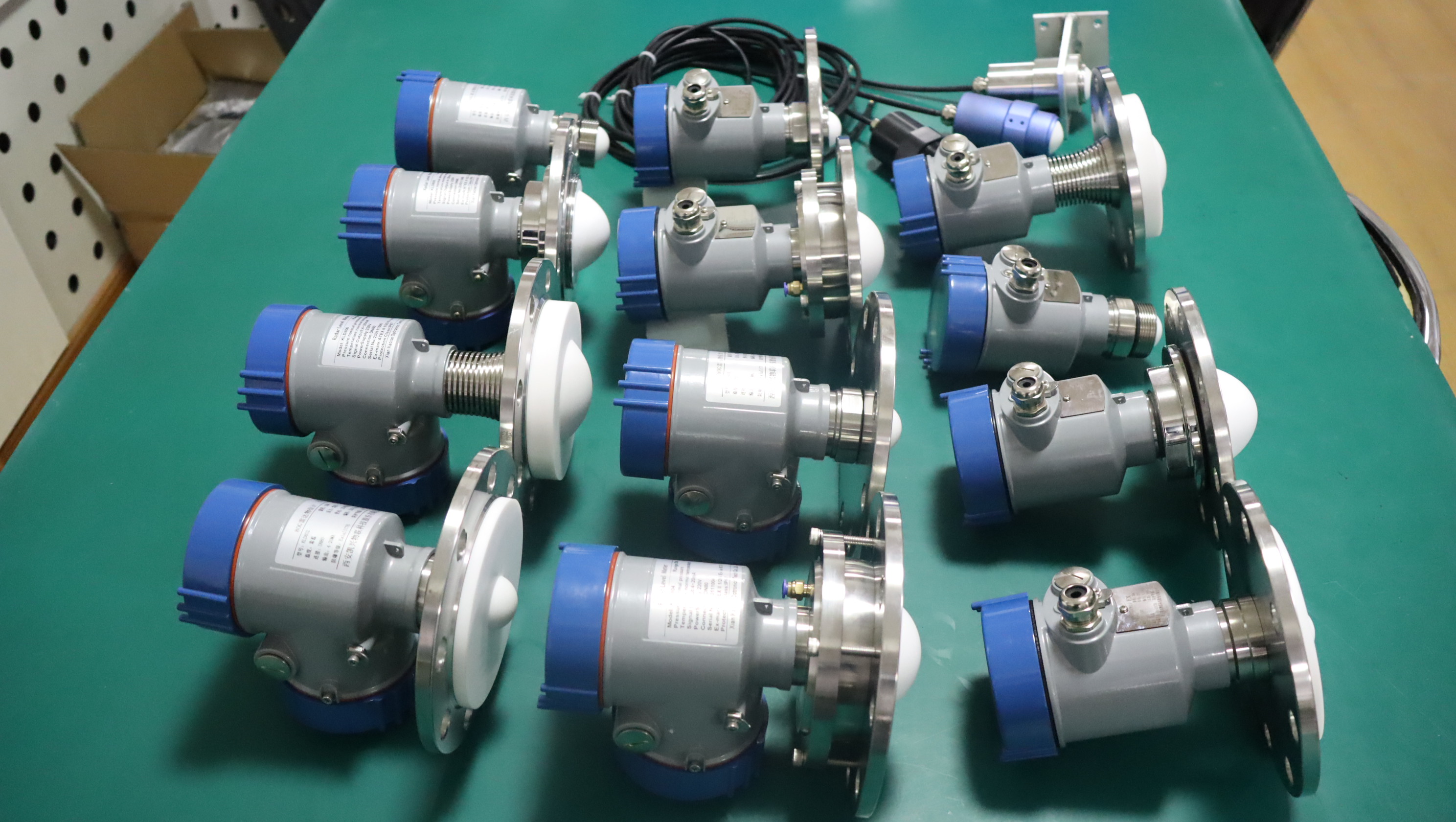
The range includes customized shell version/color, thread type(G-Thread/NPT Thread), Customized Software, prints, manual and catalog. If you are interested in installing at your side, Radar Module is available for sure.