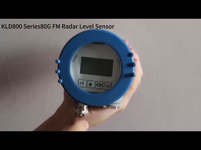
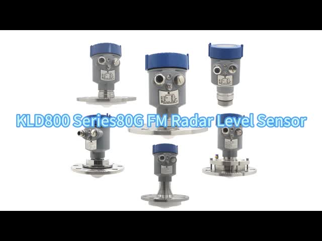
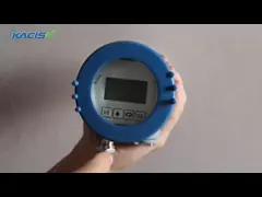
Radar Level Gauge for Sewage Treatment And Ships IP68 Water Resistance Net Weight 0.6kg
1.Introduction
1.1 Product Overview
KWL801B-RS485 radar level sensor conforms to the standard specifications outlined in national standard DB50/T 826-2017 for level meters. Its core component is designed with a fully sealed IP68 waterproofing.
The maximum measurement range of the product extends up to 40 meters, with a minimal blind spot of less than 6 cms.
Due to its higher frequency and broader bandwidth, it achieves superior accuracy. Additionally, the product includes a fixed bracket for installation.
1.2 Detection principle
Radar level sensor is based on the principle of time domain reflection (TDR). The electromagnetic pulse propagates along the cable or probe with the speed of light. When it meets the surface of the measured medium, part of the pulse of the radar level meter is reflected to form an echo return to the pulse transmitter along the same path, and the distance between the transmitter and the surface of the measured medium is In direct proportion as the propagation time of the pulse, hence the height of the level is calculated.

2.Feature
- Based on the self-developed CMOS millimeter-wave RF chip
- More compact RF architecture
- Higher signal-to-noise ratio
- Smaller dead zone
- 5GHz working bandwidth
- Higher measurement resolution and measurement accuracy
- Less influence by the interference in the installation environment
- More convenient of installation and
- Modern design of integrated flat antenna
3.Technical Specifications
| Model | KWL801B-RS485 |
| Frequency of measurement | 80GHz |
| Communication | RS485 |
| Frequency of acquisition | ≥200ms/ configurable |
| Current of operation | 12V/14mA |
| Distance measurement accuracy | ±2mm |
| Communication protocol | Modbus/ Text protocol |
| Antenna beam width | ±2.75° |
| Supply voltage | 9~24V |
| Range of measurement | 0.2~40m 0.18~30m 0.1~15/20m 0.06~3/5/10m |
| RF pulse current | 100mA/20ms |
| Working humidity | 0~95% |
| Type of thread | G thread/ customized |
| Working temperature | -40~75℃ |
| Grade of water resistance | IP68 |
| Net weight | 0.6kgs |
4.Wiring Instructions
| Red line | VCC (9~24V power supply) |
| Black line | GND |
| Yellow line | 485-A |
| Green line | 485-B |
5.Dimension
6.Installation instructions
6.1 Inspection before installation
(1) Take the sensor out of the packaging box, carefully check the packing list according to the instruction manual, and check whether the equipment accessories are complete .
(2) Carefully read the product instruction manual and product certificate .
(3) Check whether there is any damage to the appearance of the instrument, especially whether the main unit is intact, and be careful to place the main unit properly to prevent it from being knocked over.
6.2 Radar level sensor installation
6.2.1 Check before installation
Please check before installing the sensor as follows:
Whether there are trees or other debris above the medium at the installation site.
Whether the mounting bracket is installed horizontally.
When the mounting bracket cannot be installed horizontally, you need to adjust the bracket according to gradienter on the surface of the sensor to make sure the sensor is in a horizontal position.
6.2.2 Installation
(1) Ensure that the sensor is perpendicular to the medium surface.
(2) Avoid the transmitting beam from irradiating interference objects and generating false echoes.
See the following for typical working conditions:
Installation of upper thread Installation of lower thread
Ensure that the radar level meter is installed perpendicular to the medium surface.
Inclination will weaken the received signal amplitude and affect normal ranging.
Attention:
Try to keep the sensor fixed to avoid jitter when installing, and keep the surrounding environment as open as possible.
1. The distance between the sensor and the medium surface is higher than 30cm to ensure that the front face of the sensor (antenna) is perpendicular to the measuring medium.
2. The distance between the sensor and the edge of the tank, the edge of the pool, the edge of the river dam and the edge of the pool is greater than 0.5 meters;
3. Select the position of the water surface with small fluctuations to install the module (try not to install in the water injection port, outlet and other water surface with large fluctuations, the greater the water surface fluctuation, the worse the measurement accuracy)
7.MODBUS-RTU communication protocol
7.1 MODBUS protocol
1. Communication protocol hardware interface parameters
The sensor uses serial port communication, and the default parameters are as follows :
| Communication Parameters | Serial Port Level | Baud Rate | Parity Check | Data Length | Stop Bit |
| Serial Port | TTL | 9600 | None | 8 | 1 |
Timeout between frames 50ms.
2. Communication protocol format
The water level gauge communicates externally using the Modbus RTU communication protocol. Each complete data frame includes: address field, Function Code, data, and checksum. The checksum is the CRC16 check data of the data frame, with the low byte preceding the high byte. The default factory address for the sensor is 0x7F.
Request command format and radar reply data format are described as follows:
(1) Query parameter format: Function Code 0x03
Request:
| Device Address | Function Code | Register Address | Number of Registers | C R C |
| 1 Byte | 1 Byte | 2 Bytes | 2 Bytes | 2 Bytes |
Reply:
| Device Address | Function Code | Data Length | Register Value | C R C |
| 1 Byte | 1 Byte | 1 Byte | 2N Bytes | 2 Bytes |
N: numbers of registers
(2) Query parameter format: Function Code 0x04
Request:
| Device Address | Function Code | Register Address | Number of Registers | C R C |
| 1 Byte | 1 Byte | 2 Bytes | 2 Bytes | 2 Bytes |
Reply:
| Device Address | Function Code | Data Length | Register Value | C R C |
| 1 Byte | 1 Byte | 1 Byte | 2N Bytes | 2 Bytes |
N: numbers of registers
(3) Set parameter format: Function Code 0x10
Request:
| Device Address | Function Code | Register Address | Number of Registers | Data Length | Register Value | C R C |
| 1 Byte | 1 Byte | 2 Bytes | 2 Bytes | 1 Byte | 2N Bytes | 2 Bytes |
Reply:
| Device Address | Function Code | Register Address | Number of Registers | C R C |
| 1 Byte | 1 Byte | 2 Bytes | 2N Bytes | 2 Bytes |
N: numbers of registers
3. Register Address Summary Table
| Parameter Default |
| Parameter | Register Address | PLC Or Group Status Address | Support Function Code | Type Of Data | Illustrate |
| Slave Address | 0x2001 | 48194 | 0x03,0x10 | int16 | int16 For 2 Bytes Integer ; int32 For 4 Byte Integer , High 16 In Front |
| Baud Rate | 0x2002 | 48195 | 0x03,0x10 | int32 |
| Version Information | 0x2004 | 48197 | 0x03 | int32 |
| Set Up Calibration | 0x2052 | 48275 | 0x03,0x10 | int16 |
| Automatic Push Cycle | 0x2053 | 48276 | 0x03,0x10 | int16 |
| Blind Spot | 0x2044 | 48261 | 0x03 | Float(little 16) | Float(little 16) is 4 byte float , low 16th place first |
| Measuring Range | 0x2046 | 48263 | 0x03 | Float(little 16) |
| Set Current Depth | 0X2048 | 48265 | 0x03,0x10 | Float(little 16) |
| Set Up Installation High | 0x204A | 48267 | 0x03,0x10 | Float(little 16) |
| Level | 0x0A0B | 32572 | 0x04 | Float(little 16) |
| Empty Height | 0xaof | 32576 | 0x04 | Float(little 16) |
Note: The Register Address and data type of some parameters can be modified by the host computer software. After modifying the Register Address or data type, the corresponding Modbus operation instructions will also change accordingly, such as: The default instruction to read the empty height is 0x 7F 04 0A 0F 00 02 48 0E. If the register of the empty height is modified to 00 01, the instruction to read the empty height is changed to 0x 7F 04 00 01 00 02 2A 15.
4. Communication protocol command description
Note:
a. The default Device Address is 0x7F;
b. The float type data in the data adopts IEEE754 binary floating point arithmetic standard, the low 16 bits in the first (CDAB);
c. In the following example, the Register Address corresponding to each parameter is the default address. If the address of the register is modified by the host computer, the Register Address in the Modbus operation instruction should be changed accordingly;
d. In the following example, the data definition (data type/unit) of each parameter is parsed according to the default configuration. If the data definition (data type/unit) is modified through the host computer, the data reading and parsing should be modified accordingly;
7.2 Query data instruction: Function Code 0x04
7.2.1 Query measurement results - level (i.e. installation height - air height)
Request command:
| Device Address | Function Code | Register Address | Number of Registers | CRC |
| 0x7F | 0x04 | 0x0A 0B | 0x00 02 | 0x09 CF |
Reply data:
| Device Address | Function Code | Length of Data | Data | CRC |
| 0x7F | 0x04 | 0x04 | 0x00 00 41 30 | 0x09 CF |
Data definition: The default data type is float(little16) data, the default unit is meters (m), the data length is 4 bytes, and the lowest 16 bits are in the first.
Error code:
① When the installation height is not set, the level cannot be calculated, and the output 0xFC FC FC FC ;
② When the measurement results exceed the range, output 0xFF FF FF FF;
③ When the sensor is in the blind area, output 0xFE FE FE FE;
④ When the sensor echo energy is insufficient, the output 0xFD FD FD FD;
Example 1:
Request: 7F 04 0A 0B 00 02 09 CF
Reply: 7F 04 04 00 00 41 30 55 C7
The data part 0x 00 00 41 30 is converted to floating point data, that is, 11.00 m.
Example 2:
Request: 7F 04 0A 0B 00 02 09 CF
Re: 7F 04 04 FC FC FC FC D4 A2
In the data part, 0x FC FC FC FC is an error code, indicating that the mounting height is not set (the level cannot be calculated).
7.2.2 Query measurement results - air height
Request command:
| Device Address | Function Code | Register Address | Number of Registers | CRC |
| 0x7F | 0x04 | 0x0A 0F | 0x00 02 | 0x48 0E |
Reply data:
| Device Address | Function Code | Length of Data | Data | CRC |
| 0x7F | 0x04 | 0x04 | 0x31 13 40 10 | 0xAA B6 |
Data definition: The default data type is float(little16) data, the default unit is meters (m), the data length is 4 bytes, and the lowest 16 bits are in the first.
Error code:
① When the measurement results exceed the range, output 0xFF FF FF FF;
② When the sensor is in the blind area, output 0xFE FE FE FE;
③ When the sensor echo energy is insufficient, the output 0xFD FD FD FD FD;
Example 1:
Request: 7F 04 0A 0F 00 02 48 0E
Reply: 7F 04 04 31 13 40 10 AA B6
The data part 0x 31 13 40 10 is converted to floating point data, that is, 2.253 m.
Example 2:
Request: 7F 04 0A 0F 00 02 48 0E
Reply: 7F 04 04 FE FE FE F4 7B
The data part 0x FE FE FE FE is the error code, indicating that the sensor is in the blind area and no valid data can be read.
7.3 Query configuration information instruction: Function Code 0x03
7.3.1 Broadcast query slave address
Request command:
| Device Address | Function Code | Register Address | Number of Registers | CRC |
| 0xFF(broadcast) | 0x03 | 0x20 01 | 0x00 01 | 0xCB D4 |
Reply data:
| Device Address | Function Code | Length of Data | Data | CRC |
| 0x7F | 0x03 | 0x02 | 0x00 7F | 0xD1 AE |
Data definition: The data type is int16 data, and the data length is 2 Bytes.
Examples:
Request: FF 03 20 01 00 01 CB D4
Reply: 7F 03 02 00 7F D1 AE
The data part 0x 00 7F is converted to integer data, which is 127 or 0x7F.
7.3.2 Query the baud rate of the communication interface
Note: Baud rate only supports: 4800,9600,19200,38400,115200
Request command:
| Device Address | Function Code | Register Address | Number of Rregisters | CRC |
| 0x7F | 0x03 | 0x20 02 | 0x00 02 | 0x64 15 |
Reply data:
| Device Address | Function Code | Length of Data | Data | CRC |
| 0x7F | 0x03 | 0x04 | 0x00 00 25 80 | 0x7F 04 |
Data definition: The data type is int32(big) data, and the data length is 4 bytes.
Examples:
Request: 7F 03 20 02 00 02 64 15
Reply: 7F 03 04 00 00 25 80 7F 04
The data part 0x 00 00 25 80 is converted to integer data, which is 9600.
7.3.3 Query version information
Request command:
| Device Address | Function Code | Register Address | Number of Registers | CRC |
| 0x7F | 0x03 | 0x20 04 | 0x00 02 | 0x84 14 |
Reply data:
| Device Address | Function Code | Length of Data | Data | CRC |
| 0x7F | 0x03 | 0x04 | 0x20 23 09 08 | 0x99 A8 |
Data definition: The data type is int32 data, and the data length is 4 bytes. Version numbers were coded in BCD format.
Examples:
Request: 7F 03 20 04 00 02 84 14
Reply: 7F 03 04 20 23 09 08 99 A8
The data part is 0x 20230908, and the data is encoded in BCD format, namely the version number is 20230908.
7.3.4 Query calibration parameters
Request command:
| Device Address | Function Code | Register Address | Number of Registers | CRC |
| 0x7F | 0x03 | 0x20 52 | 0x00 01 | 0x24 05 |
Reply data:
| Device Address | Function Code | Length of Data | Data | CRC |
| 0x7F | 0x03 | 0x02 | 0x00 10 | 0x91 82 |
Data definition: The data type is int16 data, the unit is millimeter (mm), and the data length is 2 Bytess.
Examples:
Request: 7F 03 20 52 00 01 24 05
Reply: 7F 03 02 00 10 91 82
The data part 0x 00 10 is converted to integer data, that is, 16 mm.
7.3.5 Query automatic push cycle
Note: When the automatic push period is >=300ms, the sensor will automatically push data. When the installation height is not set ( level cannot be calculated), push the air height data; When the mounting height is set, push the level data.
Request command:
| Device Address | Function Code | Register Address | Number of Registers | CRC |
| 0x7F | 0x03 | 0x20 53 | 0x00 01 | 0x75 C5 |
Reply data:
| Device Address | Function Code | Length of Data | Data | CRC |
| 0x7F | 0x03 | 0x02 | 0x03 E8 | 0x90 F0 |
Data definition: The data type is int16 data, the unit is milliseconds (ms), and the data length is 2 Bytes.
Examples:
Request: 7F 03 20 53 00 01 75 C5
Reply: 7F 03 02 03 E8 90 F0
Where the data part 0x 03 E8 is converted to integer data, that is, 1000 ms.
7.3.6 Query blind area
Request command:
| Device Address | Function Code | Register Address | Number of Registers | CRC |
| 0x7F | 0x03 | 0x20 44 | 0x00 02 | 0x85 C0 |
Reply data:
| Device Address | Function Code | Length of Data | Data | CRC |
| 0x7F | 0x03 | 0x04 | 0x6D B7 3E AB | 0x99 61 |
Data definition: The default data type is float(little16) data, the default unit is meters (m), and the data length is 4 bytes.
Examples:
Request: 7F 03 20 44 00 02 85 C0
Reply: 7F 03 04 6D B7 3E AB
The data part 0x 6D B7 3E AB was converted to floating-point type data, that is, 0.334 m.
7.3.7 Query range
Request command:
| Device Address | Function Code | Register Address | Number of Registers | CRC |
| 0x7F | 0x03 | 0x20 46 | 0x00 02 | 0x24 00 |
Reply data:
| Device Address | Function Code | Length of Data | Data | CRC |
| 0x7F | 0x03 | 0x04 | 0x00 00 42 20 | 0x55 4C |
Data definition: The default data type is float(little16) data, the default unit is meters (m), and the data length is 4 bytes.
Examples:
Request: 7F 03 20 46 00 02 24 00
Reply: 7F 03 04 00 00 42 20 55 4C
The data part 0x 00 00 42 20 is converted to floating point data, that is, 40.0m.
7.3.8 Check the depth at installation
Note: The water depth at the time of installation is used to calculate the installation height. Installation height = water depth at installation + real time height at installation. When setting the water depth at the time of installation, the installation height is automatically calculated and saved to the configuration.
Request command:
| Device Address | Function Code | Register Address | Number of Registers | CRC |
| 0x7F | 0x03 | 0x20 48 | 0x00 02 | 0x45 C3 |
Reply data:
| Device Address | Function Code | Length of Data | Data | CRC |
| 0x7F | 0x03 | 0x04 | 0x47 AE 40 B1 | 0xE0 D5 |
Data definition: The default data type is float(little16) data, the default unit is meters (m), and the data length is 4 bytes.
Examples:
Request: 7F 03 20 48 00 02 45 C3
Reply: 7F 03 04 47 AE 40 B1 E0 D5
The data part 0x 47 AE 40 B1 was converted to floating point data, that is, 5.54 m.
7.3.9 Check installation height
Note: Set the mounting height, which is used to calculate the level. Real-time level = installation height - real time height. At the same time, installation height = water depth at installation + height at installation time. Therefore, when setting the installation height, the water depth during installation will be automatically calculated and saved to the configuration.
Request command:
| Device Address | Function Code | Register Address | Number of Registers | CRC |
| 0x7F | 0x03 | 0x20 4A | 0x00 02 | 0xE4 03 |
Reply data:
| Device Address | Function Code | Length of Data | Data | CRC |
| 0x7F | 0x03 | 0x04 | 0x8A 64 41 2A | 0xBE 7C |
Data definition: The default data type is float(little16) data, the default unit is meters (m), and the data length is 4 bytes.
Examples:
Request: 7F 03 20 4A 00 02 E4 03
Reply: 7F 03 04 8A 64 41 2A BE 7C
The data part 0x 8A 64 41 2A is converted to floating point data, that is, 10.65m.
7.4 Set instruction: Function Code 0x10
7.4.1 Set the slave address
Request command:
| Device Address | Function Code | Register Address | Number of Registers | Length of Data | Data | CRC |
| 0x7F | 0x10 | 0x20 01 | 0x00 01 | 0x02 | 0x00 01 | 0x6E 21 |
Reply data:
| Device Address | Function Code | Register Address | Number of Registers | CRC |
| 0x7F | 0x10 | 0x20 01 | 0x00 01 | 0x51 D7 |
Data definition: The data type is int16 data, and the data length is 2 Bytess.
Examples:
Request: 7F 10 20 01 00 01 02 00 01 6E 21
The data part 0x 00 01 is converted to integer data, that is, 1 or 0x01.
Reply: 7F 10 20 01 00 01 51 D7
7.4.2 Set baud rate of communication interface
Note: Baud rate only supports: 4800,9600,19200,38400,115200
Request command:
| Device Address | Function Code | Register Address | Number of Registers | Length of Data | Data | CRC |
| 0x7F | 0x10 | 0x20 02 | 0x00 02 | 0x04 | 0x00 01 C2 00 | 0x75 3E |
Reply data:
| Device Address | Function Code | Register Address | Number of Registers | CRC |
| 0x7F | 0x10 | 0x20 02 | 0x00 02 | 0xE1 D6 |
Data definition: The data type is int32 data, and the data length is 4 bytes.
Examples:
Request: 7F 10 20 02 00 02 04 00 01 C2 00 75 3E
The data part 0x 00 01 C2 00 is converted to integer data, which is 115200.
Reply: 7F 10 20 02 00 02 E1 D6
7.4.3 Setting calibration parameters
Request command:
| Device Address | Function Code | Register Address | Number of Registers | Length of Data | Data | CRC |
| 0x7F | 0x10 | 0x20 52 | 0x00 01 | 0x02 | 0x00 01 | 0xA2 4E |
Reply data:
| Device Address | Function Code | Register Address | Number of Registers | CRC |
| 0x7F | 0x10 | 0x20 52 | 0x00 01 | 0xA1 C6 |
Data definition: The data type is int16 data, the unit is millimeter (mm), and the data length is 2 Bytes.
Examples:
Request: 7F 10 20 52 00 01 02 00 10 A2 4E
The data part 0x 00 10 is converted to integer data, that is, 16 mm.
Reply: 7F 10 20 52 00 01 A1 C6
7.4.4 Set automatic push cycle
Note: When the automatic push period is >=300ms, the sensor will automatically push data. When the installation height is not set ( level cannot be calculated), push the air height data; When the mounting height is set, push the level data.
Request command:
| Device Address | Function Code | Register Address | Number of Registers | Length of Data | Data | CRC |
| 0x7F | 0x10 | 0x20 53 | 0x00 01 | 0x02 | 0x03 E8 | 0xA2 ED |
Reply data:
| Device Address | Function Code | Register Address | Number of Registers | CRC |
| 0x7F | 0x10 | 0x20 53 | 0x00 01 | 0xF0 06 |
Data definition: The data type is int16 data, the unit is milliseconds (ms), and the data length is 2 Bytes.
Examples:
Request: 7F 10 20 53 00 01 02 03 E8 A2 ED
Where the data part 0x 03 E8 is converted to integer data, that is, 1000 ms.
Reply: 7F 10 20 53 00 01 F0 06
7.4.5 Set the water depth at the time of installation
Note: The water depth at the time of installation is used to calculate the installation height. Installation height = water depth at installation + real time height at installation. When setting the water depth at the time of installation, the installation height is automatically calculated and saved to the configuration.
Request command:
| Device Address | Function Code | Register Address | Number of Registers | Length of Data | Data | CRC |
| 0x7F | 0x10 | 0x20 48 | 0x00 02 | 0x04 | 0x47 AE 40 B1 | 0x75 30 |
Reply data:
| Device Address | Function Code | Register Address | Number of Registers | CRC |
| 0x7F | 0x10 | 0x20 48 | 0x00 02 | 0xC0 00 |
Data definition: The default data type is float(little16) data, the default unit is meters (m), and the data length is 4 bytes.
Examples:
Request: 7F 10 20 48 00 02 04 47 AE 40 B1 75 30
The data part 0x 47 AE 40 B1 was converted to floating point data, that is, 5.54 m.
Reply: 7F 10 20 48 00 02 C0 00
7.4.6 Set the installation height
Note: The installation height is the distance from the sensor to the 0 object level. If the current water depth is 2 meters and the air height is 4 meters, the installation height is 6 meters. Set the mounting height, which is used to calculate the level. Real-time level = installation height - real time height. At the same time, installation height = water depth at installation + height at installation time. Therefore, when setting the installation height, the water depth during installation will be automatically calculated and saved to the configuration.
Request command:
| Device Address | Function Code | Register Address | Number of Registers | Length of Data | Data | CRC |
| 0x7F | 0x10 | 0x20 4A | 0x00 02 | 0x04 | 0x8A 64 41 2A | 0xAA 40 |
Reply data:
| Device Address | Function Code | Register Address | Number of Registers | CRC |
| 0x7F | 0x10 | 0x20 4A | 0x00 02 | 0x61 C0 |
Data definition: The default data type is float(little16) data, the default unit is meters (m), and the data length is 4 bytes.
Note: Setting the mounting height to 0 will clear the mounting height/water depth configuration at installation.
Examples:
Request: 7F 10 20 4A 00 02 04 8A 64 41 2A AA 40
The data part 0x 8A 64 41 2A is converted to floating point data, that is, 10.65m.
Reply: 7F 10 20 4A 00 02 61 C0
7.5 Text protocol
7.5.1 Communication protocol hardware interface parameters
The water level meter adopts serial communication, and the default parameters are as follows:
| Communication parameters | Serial port level | Baud rate | Parity check | Length of Data | Stop position |
| Serial port | TTL | 9600 | - | 8 | 1 |
The timeout time was 50ms for each frame interval.
7.5.2 Description of communication protocol commands
Note: "n" represents a newline, corresponding to the hexadecimal number 0x0A. After the setup command configuration is successful, the configuration will be saved in Flash, and no reconfiguration is needed to restart the power outage.
The command error response is as follows:
| Command error response | Description |
| This AT cmd is errorn | Instruction error |
| This AT cmd is no existn | Instruction does not exist |
| This AT cmd is exist,but not allow to operaten | Instructions exist but are not allowed to operate |
| This AT cmd is exist,but value is errorn | Incoming parameter error |
1.Read the real spatio-temporal height
Unit: Meter (m)
| | Instruction | Description |
| Send | AT+REALAIRHEIGHTn | Read the real spacetime height |
| Reply | REALAIRHEIGHT=2.212mn | The current real spacetime height is 2.212 meters |
| Reply | REALAIRHEIGHT=OutRangen | Out of range |
| Reply | REALAIRHEIGHT=InBlindZonen | The sensor is in the blind area |
| Reply | REALAIRHEIGHT=LackEnergyn | The echo energy is insufficient |
2.Read the real-time level
Unit: Meter (m)
The calculation method of the level is: installation height - air height
| | Instruction | Description |
| Send | AT+REALWATERDEPTHn | Read real-time level |
| Reply | REALWATERDEPTH=7.789m | The current real-time level is 7.789 meters |
| Reply | REALWATERDEPTH=OutRangen | Out of range |
| Reply | REALWATERDEPTH=InBlindZonen | The sensor is in the blind area |
| Reply | REALWATERDEPTH=LackEnergyn | The echo energy is insufficient |
| Reply | REALWATERDEPTH=No Set InstallHeightn | The installation height is not set |
3.Water depth at installation
Unit: Meter (m)
Note: The water depth at the time of installation is used to calculate the installation height. Installation height = water depth at installation + real time height at installation. When setting the water depth at the time of installation, the installation height is automatically calculated and saved to the configuration.
Read the water depth at installation:
| | Instruction | Description |
| Send | AT+INSTALLWATERDEPTHn | Read the water depth at installation |
| Reply | INSTALLWATERDEPTH=4.60mn | Water depth at installation is 4.60 meters |
Set the water depth at the time of installation:
| | Instruction | Description |
| Send | AT+INSTALLWATERDEPTH=4.6n | Water depth is set to 4.6 m during installation |
| Reply | AT+INSTALLWATERDEPTH=4.6n OKn | Operation successful |
4.Height of installation
Unit: Meter (m)
Note: Set the mounting height, which is used to calculate the level. Real-time level = installation height - real time height. At the same time, installation height = water depth at installation + height at installation time. Therefore, when setting the installation height, the water depth during installation will be automatically calculated and saved to the configuration.
Read mounting height:
| | Instruction | Description |
| Send | AT+INSTALLHEIGHTn | Read mounting height |
| Reply | INSTALLHEIGHT=9.72mn | Water depth at installation is 9.72 meters |
Set mounting height:
| | Instruction | Description |
| Send | AT+INSTALLHEIGHT=9.72n | Set the installation height to 9.72 m |
| Reply | AT+INSTALLHEIGHT=9.72n OKn | Operation successful |
Note: Setting the mounting height to 0 will clear the configuration for mounting height and water depth at installation.
5.Read the version number
| | Instruction | Description |
| Send | AT+VERSIONn | Read version number |
| Reply | VERSION=20230908n | The version number is 20230908 |
6.Read range
Unit: Meter (m)
| | Instruction | Description |
| Send | AT+RANGEn | Read range |
| Reply | RANGE=40.00mn | The range is 40 meters |
7.Read blind area
Unit: Meter (m)
| | Instruction | Description |
| Send | AT+BLINDZONEn | Read blind area |
| Reply | BLINDZONE=0.335mn | The blind zone is 0.335 meters |
8.Software reset (reboot)
| | Instruction | Description |
| Send | AT+BOOTn | Software reset |
| Reply | AT+BOOTn OKn | Operation successful |
9.Factory data reset
| | Instruction | Description |
| Send | AT+DEFAULTn | Factory data reset |
| Reply | AT+DEFAULTn OKn | Operation successful |
10.Frequency of acquisition
Unit: milliseconds (ms)
Note: The default acquisition frequency is 300ms, and the acquisition frequency can only be adjusted to 200ms at the earliest. (If the acquisition frequency jumps too fast, the speed of responding to the reply instructions will be slow, and the sending instructions may be incomplete, resulting in no response. In this case, the instruction can be sent again.)
Read acquisition frequency:
| | Instruction | Description |
| Send | AT+COLLECTFREQn | Read acquisition frequency |
| Reply | COLLECTFREQ=200n | The acquisition frequency is 200 ms/cyclel |
Set collection frequency:
| | Instruction | Description |
| Send | AT+COLLECTFREQ=500n | Set the acquisition frequency to 500 ms/cycle |
| Reply | AT+COLLECTFREQ=500n OKn | Operation successful |
11.Baud rate
Read baud rate:
| | Instruction | Description |
| Send | AT+BAUDRATEn | Read baud rate |
| Reply | BAUDRATE=9600n | The baud rate is 9600 |
Set baud rate
| | Instruction | Description |
| Send | AT+BAUDRATE=115200n | Set the baud rate to 115200 |
| Reply | AT+BAUDRATE=115200n OKn | Operation successful |
12.Calibration parameters
Unit: Millimeter (mm)
Real spatio-temporal height = sampling value -calibration parameter. Therefore, when the real space-time height is larger than a fixed value, it can be calibrated by adjusting the quasi-parameters.
Read calibration parameters:
| | Instruction | Description |
| Send | AT+CALIBRATIONn | Read calibration parameters |
| Reply | CALIBRATION=16mmn | The calibration parameter is 16mm |
Setting calibration parameters:
| | Instruction | Description |
| Send | AT+CALIBRATION=30n | Set the calibration parameter to 30 mm |
| Reply | AT+CALIBRATION=30n OKn | Operation successful |
13.Automatic push cycle
Unit: milliseconds (ms)
Note: When the automatic push period is >=300ms, the sensor will automatically report the real-time data. Among them, when the installation height (or water depth during installation) is set, the real-time data reported automatically is the real-time level; If the installation height is not set (or the water depth during installation), the real-time data reported automatically is the real time height.
Read the automatic push cycle:
| | Instruction | Description |
| Send | AT+AUTOOUTDATACYCLEn | Read the automatic push cycle |
| Reply | AUTOOUTDATACYCLE=100n | Automatic push cycle is 100 ms (less than 200 ms, no automatic push data) |
Set the automatic push cycle:
| | Instruction | Description |
| Send | AT+AUTOOUTDATACYCLE=200n | Set the automatic push period to 200 milliseconds |
| Reply | AT+AUTOOUTDATACYCLE=200n OKn | Operation successful
|