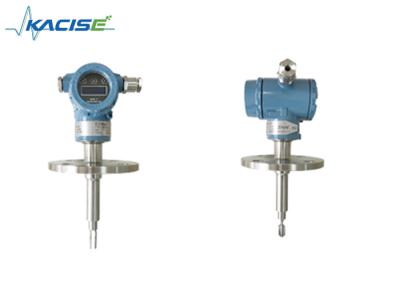
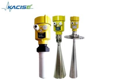
Capacitive level sensor of KSLV605

1 General Description
Capacitive intelligent liquid level sensor is a liquid level (material level) transmitter that can be used for liquid, oil, solid, interface and measurement. There are no moving parts, the reliability is greatly improved, it is not affected by water vapor, dust or condensation, and has the advantages of stable and reliable long-term operation, high sensitivity, good linearity, high temperature resistance, high pressure resistance, etc. The intelligent liquid level meter is a two-wire (loop powered) 4~20mADC measurement signal, easy to adjust, wireless transmission, 485 transmission, etc. Can be widely used in petroleum, chemical, metallurgy, electric power, paper, pharmaceutical and other fields.
2 Feature
Modbus protocol is easy to integrate.
Simple structure without any movable or elastic components, so it has high reliability and minimal maintenance. Under normal circumstances, it is not necessary to carry out routine large, medium and small maintenance.
A variety of signal outputs are convenient for different system configurations.
Suitable for level measurement of high temperature and high pressure containers, and the measured value is not affected by the temperature, specific gravity of the liquid to be measured, and the shape and pressure of the container.
It is especially suitable for the measurement of strong corrosive liquids such as acid and alkali.
Perfect overcurrent, overvoltage and power supply polarity protection.
Wireless level sensor has wireless remote transmission function.
Can measure any medium.
3 Specification
Detection range: 0.1~30m
Capacitance measurement range: 10PF~500PF
Accuracy: 0.1 class, 0.2 class, 0.5 class, 1 class
Pressure range: -0.1MPa~32MPa
Probe temperature resistance: -50~250℃
Ambient temperature: -40~85℃
Storage temperature: -55℃~+125℃
Output signal: 4~20mA, 485 communication, etc.
The communication distance of wireless output level sensor is less than 200 meters, and the power supply voltage is 3.3-36V (optional battery power supply)
Power supply voltage: 5~36V DC
Level sensor material: 316 stainless steel, 1Gr18Ni19Ti or PTFE
Long-term stability: ≤0.1%FS/year,
Temperature drift: ≤0.01%FS/ ℃ (within the range of 0~70 ℃)
Explosion-proof grade: ExibIICT6
Protection level: IP67
4 Structure
Capacitive liquid level sensors have different structures due to different application occasions and parameters, but in general, its main structure can be roughly divided into two parts, namely the sensor part and the transmitter part. as the picture shows:

A in the picture shows the sensor, which directly probes into the container equipment or measures in the measured medium of the meter tube
B and C in the figure are the gas phase and liquid phase connection flanges of the liquid level measurement and control instrument, which are used for the connection of the equipment flanges, and the liquid and pressure in the equipment are drawn to the measuring cylinder.
D in the figure shows the measuring cylinder of the liquid level measurement and control instrument, which can form a capacitance with the sensor electrode.
E shown in the figure is the sewage flange, which can regularly discharge the dirt in the liquid level measurement and control instrument to the outside, keep the inside of the measuring tube of the liquid level measurement and control instrument clean, and prevent the sensor from adhering to the dirt.
F shown in the figure is the transmitter, which is a conversion device from capacitance to standard current signal, and is the central part of the entire liquid level measurement and control instrument. Its main function is to receive the capacitance change increment caused by the liquid level change sent by the sensor, and then After conversion, it outputs 4-20mADC standard current signal. This transmitter adopts military integrated devices, with low power consumption, high temperature resistance, strong reliability, and meets the requirements of intrinsic safety.
Note: There is a sealing part between the transmitter and the measuring tube, which is composed of several seals, which can ensure that the measured medium is in contact with the sensor but will not leak out, causing harm. This section is an important sealing part, please do not disassemble it without the consent of the manufacturer to avoid accidents.
5 Display

6 Wiring
KSLV606 (display model) has two ways of wiring: one is RS485, the other is 4-20mA.
1) RS485
2) 4-20mA


After installation, when using it for the first time, make sure to open the gas phase valve first, and then open the liquid phase valve to ensure that the liquid level will not fluctuate violently, causing measurement errors.
In addition, it should be ensured that the connecting cable joints are in good contact and anti-corrosion. In long-term use, pay attention to regular sewage discharge, so as to avoid the accumulation of dirt and affect the performance of the instrument. Taking common copper liquid, C-carbon liquid, Baohe hot water tower, sewage pool and other dirty media as an example, it should be guaranteed to discharge 1 to 2 times a week, while the cleaner medium should be discharged 1 to 2 times a month.The transmitter housing should be tightly wrapped to prevent water, corrosive medium or gas from entering, and it is forbidden to collide with external force and dismantle it by non-professionals. There are three common wiring methods for transmitters: as shown in (a) (b) (c)


As shown in the figure above, there are three wiring methods for the transmitter of the liquid level measurement and control instrument. Figure (a) shows the wiring diagram of the transmitter directly and the digital display meter. Figure (b) shows the wiring diagram of the transmitter and the DCS control system. The control system supplies 24V and is connected to the transmitter. Figure (c) shows the connection diagram of the transmitter powered by the safety barrier. Users can refer to the above three wiring methods during installation.