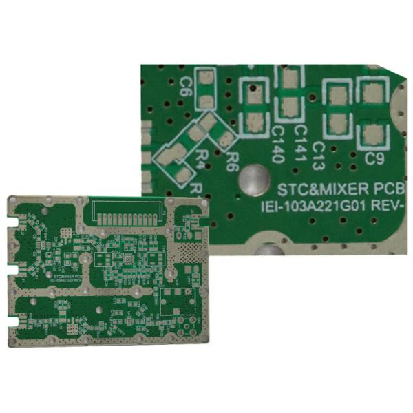
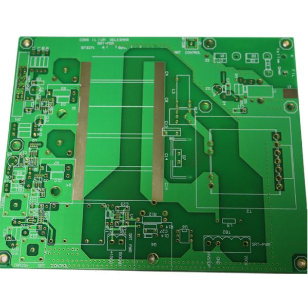
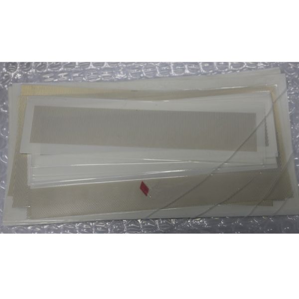
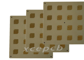
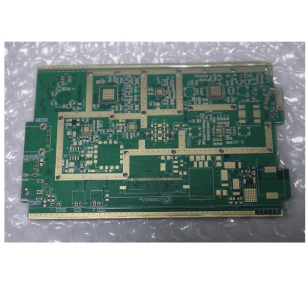
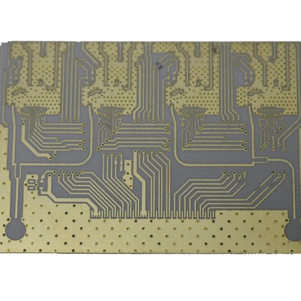
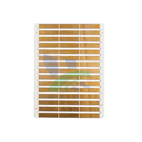
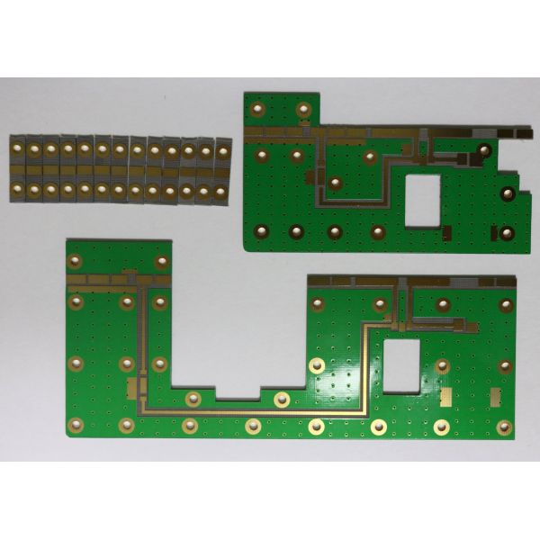
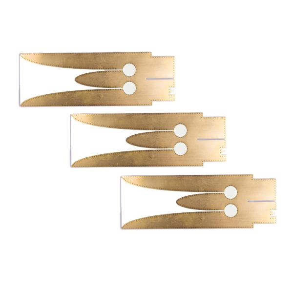
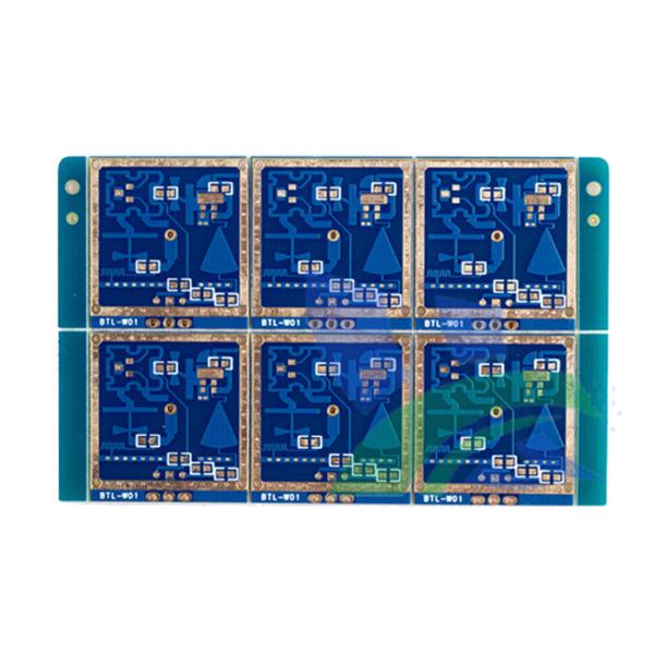
HF 4003C Multiayer Rogers PCB Printed Circuit Boards , 6 layer
Rogers 4003C knowledge:
Volume production of microwave circuit assemblies requires fast, reliable and effi cient methods of attaching discrete microwave components to the circuit board. These could include simple two-lead devices such as resistors or diodes, or complex multi-lead MICs. Bonding techniques used for conventional epoxy glass grade laminates have been used with limited success on PTFE based laminates. However, conventional epoxy glass grade parameters are generally acceptable for the Rogers RO4000® series high frequency laminates. This application note is intended to present a general guide for device attachment to RT/duroid® and RO4000 high frequency laminates.
RT/duroid Laminate Characteristics RT/duroid laminates are random glass fi ber reinforced PTFE or ceramic fi lled PTFE materials. PTFE is a soft, waxy, thermoplastic fl uoropolymer. The glass or ceramic reinforcement adds dimensional stability and increases the hardness but the laminates are, in general, much softer than the low frequency hardboards, such as glass/epoxy. PTFE is a thermoplastic rather than a thermosetting resin. At elevated temperatures the substrate will readily deform and take a permanent set. Lead attachment methods must therefore minimize the pressure applied to the dielectric, particularly at elevated temperatures.
Special:
Material: Rogers 4003C 0.203mm+FR4
Special requirements: blind hole
0.1mm BGA hole need to be filled
Rogers 4003C fr4 Stack up files:
Quick detail:
Model:XCEBR-6
Size: 16*5cm
Copper THK:35UM
Color: Green
Surface finish:Immersion gold,ENIG
6 layer 0.693mm thickness
Green solder mask,white silk screen
Line space and width:6mil
Certification:ISO9001/SGS/UL
Delivery time:7 working days
Application:
Automotive,Backplanes,RF / Microwave,High End Computing
Signal Integrity,Medical,Military,Mobile Devices / Wireless Handsets
Railway,Servers,Switches/Routers,Thermal Management,Wireless Infrastructure
Rogers 4003 PCB Testing Procedures For PCB Board
---We perform multiple quality assuring procedures before shipping out any PCB board. These include:
* Visual Inspection
* Flying probe
* Bed of nails
· * Impedance control
· * Solder-ability detection
* Digital metallograghic microscope
· *AOI (Automated Optical Inspection)
High Frequency Rogers 6-layer PCB
Based on a variety of parameters, HF signals are reflected on circuit board, meaning that the impedance (dynamic resistance) varies with respect towards the sending component. To prevent such capacitive effects, all parameters must be exactly specified, and implemented with the highest amount of approach manage.
Vital for the impedances in high frequency printed circuit boards are principally the conductor trace geometry, the layer buildup, along with the dielectric continuous (er) on the supplies applied.
Materials used for HF circuit boards
For many applications, it is sufficient to use Rogers material with an appropriate layer buildup. In addition, we process high-frequency materials with improved dielectric properties. These have a very low loss factor, a low dielectric constant, and are primarily temperature and frequency independent.
Additional favourable properties are high glass transition temperature, an excellent thermal durability, and very low hydrophilic rate.
We use (among others) Rogers or PTFE materials (for example, Teflon from DuPont) for impedance controlled high frequency circuit boards. Sandwich buildups for material combinations are also possible.
The increasing complexity of electronic components and switches continually requires faster signal flow rates, and thus higher transmission frequencies. Because of short pulse rise times in electronic components, it has also become necessary for high frequency (HF) technology to view conductor widths as an electronic component.
Shipping Method and Payment terms:
1. By DHL, UPS, FedEx, TNT using clients account.
2. We suggest you using our DHL, UPS, FedEx, TNT forwarder.
3. By EMS (Usually for Russia Clients), price is high.
4. By sea for mass quantity according to customer's requirement.
5. By customer's Forwarder
6. By Paypal, T/T, West Union, etc.
Rogers 4003 PCB Parameter
o. | Item | Spec |
1 | Layers | 6 layers |
2 | Max working panel area | 457 x 610 mm |
3 | Min board thickness | 4 layer: 0.40mm |
6 layer: 0.80mm | ||
8 layer: 1.00mm | ||
10 layer: 1.20mm | ||
4 | Min trace width | 0.10mm |
5 | Min spacing | 0.10mm |
6 | Min hole diameter | 0.20mm |
7 | Min Copper thickness in hole | 0.020mm |
8 | PTH size tolerance | ±0.05mm |
9 | NPTH size tolerance | ±0.025mm |
10 | Hole position tolerance | ±0.05mm |
11 | Dimension tolerance | ±0.1mm |
12 | Min solder mask dam | 0.08mm |
13 | Insulation resistance | 1E+12Ω (normal condition) |
14 | Max Board thickness/Hole size Rate | '10:01 |
15 | Thermal shock endurance | 288 3 times in 10sec |
16 | Max Board twist and wrap | ≤0.7% |
17 | High Vlotage endurance | 1.3KV/mm |
18 | Copper foil peel off endurance | 1.4N/mm |
19 | Hardness of resist ink | ≥6H |
20 | Flame resistance | 94V-0 |
21 | Impedance control | ±5% |
Place of Origin: | China |
Brand Name: | XCE |
Model Number: | XCEBR-6 |
Port | Shenzhen,HongKong |
Minimum Order Quantity: | 1pcs |
Price: | Please send gerber file for accurate price |
Packaging Details: | Inner:vacuum packed bubble bag Outer:carton box |
Delivery Time: | 3-8 days |
Payment Terms: | T/T,western union,paypal,L/C |
Supply Ability: | 1, 000, 000PCS/week |