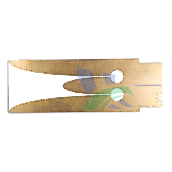
Creating Successful Connections with High Frequency PCBs
The telecom industry is in continual need of High Frequency printed circuit boards that can provide high speed solutions for a variety of products and systems.
At Xinchenger, we work tirelessly to produce Rogers,Taconic,F4B printed circuit boards that can provide solutions for the continuously changing requirements of the telecom industry.
As most telecom applications are extremely large and spaced out, we recommend double sided Rogers printed circuit boards. Xinchenger can build RF PCBs with more than 24 layers for effective use in an application.
Custom Rogers,Taconic,Isola,F4B PCBs are our forte. We enjoy working with clients who can give us a challenge. Our Rogers and other high frequency PCBs can be created in many shapes and size. We have the capabilities to create RF printed circuit boards with large panel sizes up to 18" x 24".
It is mainly composed of a GPS receiver and a satellite antenna.The GPS receiver is divided into a geodetic type, a full station type, a timed type, a handheld type, and an integrated type according to the model, and is divided into a vehicle type, a ship type, and an onboard type according to the purpose. Star-loaded, shell-mounted.
Technology | Standard Tech | Leading Edge Tech |
Line Width / Space Phototool | .004 /.0035 | .003 /.003 |
Minimum Plated hole ( mech. Drill size ) | .008 | .006 |
Minimum Pad Diameter | .018 | .014 |
SMT pitch | .020 | .016 |
BGA pitch | 1mm | 0.8mm |
Plane clearance ( over drill size ) | .018 | .014 |
Aspect Ratio | 10:1 | 12:1 |
Maximum number of layers | 20 | 24 |
Minimum Web ( Dam ) | .003 | .002 |
Legend ( Line width ) | 5 | 4 |
Via Filling / Conductive and Non- Conductive Planarization | No | Yes |
Micro-via ( Blind/Buried ) | Yes | Yes |
Micro Via Laser Drilling | No | No |
Flex / Rigid - Flex | No | Yes |
Material Requirements | Standard Tech | Leading Edge Tech |
Panel Size ( Max ) | 21 X 24 | 21 X 24 |
Core Thickness ( Min ) | .004 | .0035 |
Panel Thickness ( Max ) | .200 | .250 |
Copper Wt ( Min ) | H Oz | ¼ Oz |
Copper Wt ( Max ) | 4 Oz | 4 Oz |
High Frequency | Standard Tech | Leading Edge Tech |
( RoHS ) IS410/370 HR/MEM-1755 | Yes | Yes |
Nelco N4000-13 | Yes | Yes |
Rogers 4000 Series | Yes | Yes |
Arlon 25 Series | Yes | Yes |
Teflon | Yes | Yes |
Isola FR-408 | Yes | Yes |
HDI Materials | Standard Tech | Leading Edge Tech |
Thermount | No | Yes |
RCC ( Resin Coated Copper Foil ) | No | Yes |
CAF/Halogen Free | Yes | Yes |
Metal Core Bonding | No | Yes |
Finishes | Standard Tech | Leading Edge Tech |
Hot –Air-Solder-Level ( HASL ) | .0003 | .0002 |
Immersion Gold ( ROHS/Lead Free ) | 3 – 5 U Inch | 3 – 5 U Inch |
Immersion Silver ( ROHS/Lead Free ) | 8 – 14 U Inch | 8 – 14 U Inch |
Immersion Tin ( ROHS/Lead Free ) | No | Yes |
Electrolytic Soft Gold | Outsource | 30 U Inch |
Electrolytic Hard Gold | Outsource | 50 U Inch |
Gold Tabs | 30 – 50 U Inch | 30 – 50 U Inch |
Lead Free HASL ( ROHS/Lead Free ) | No | Yes |
Soldermask | Standard Tech | Leading Edge Tech |
Minimum Web ( Dam ) | .003 | .002 |
Via Plug – Secondary Screen | Yes | Yes |
Tolerances | Standard Tech | Leading Edge Tech |
Layer To Layer Registration | +/- .005 | +/- .004 |
Hole Locations | +/- .003 | +/- .003 |
Line Width ( Half Ounce Copper ) | +/- .001 | +/- .0007 |
Board Thickness | +/- 10% | +/- 8% |
Controlled Impedance | +/- 10% | +/- 10% |
Warpage | .70% | .50% |
Electrical Testing | Standard Tech | Leading Edge Tech |
Double Sided / Clamshell | .015 Pitch | .015 Pitch |
Flying Probe Tester | .006 Pitch | .006 Pitch |