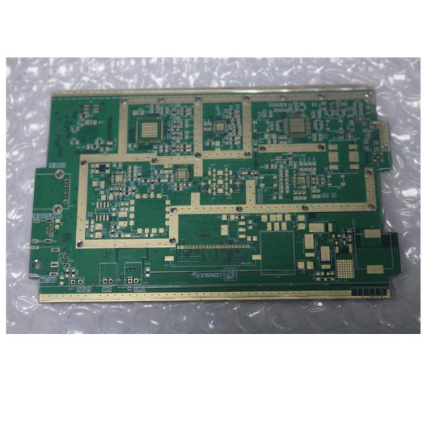
The increasing complexity of electronic components and switches continually requires faster signal flow rates, and thus higher transmission frequencies. Because of short pulse rise times in electronic components, it has also become necessary for high frequency (HF) technology to view conductor widths as an electronic component.
Depending on various parameters, HF signals are reflected on circuit board, meaning that theimpedance (dynamic resistance) varies with respect to the sending component. To prevent such capacitive effects, all parameters must be exactly specified, and implemented with the highest level of process control.
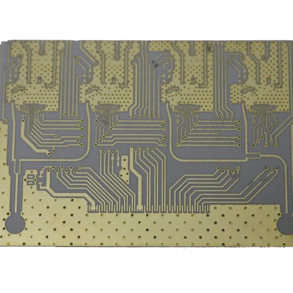
Critical for the impedances in high frequency circuit boards are principally the conductor trace geometry, the layer buildup, and the dielectric constant (er) of the materials used.
Capability | Standard | Advanced |
Laminate materials | FR4 / FR1 / CEM-3 / CEM-1 / Aluminum | Teflon / High-TG / Rogers / Taconic |
Surface Finish |
HASL (vertical & Horizontal), Lead Free HASL, HASL+Gold Finger, OSP/Entek, ENIG, ENEPIG, Immersion Tin(ISn) ,Immersion Silver(IAg), |
HASL (vertical & Horizontal), Lead Free HASL, HASL+Gold Finger, OSP/Entek, ENIG, ENEPIG, Immersion Tin(ISn) ,Immersion Silver(IAg), Carbon Ink, Hard Gold(Flash Gold), Soft Gold |
Min. Thickness for inner layers | 0.020"-0.125" | 0.003”(0.07mm) |
Board layers | 1-12 Layers | 1-24 Layers |
Board Thickness | 0.5mm-3mm | 0.2mm-7mm |
Copper weight | 0.5 oz – 3 oz | 0.5 oz – 6 oz |
Minimum Trace Width / Spacing | 0.004"/0.004" | 0.003"/0.003" |
Solder Mask Color | Green,Blue,Black,Red,Yellow,White | customized |
Drill deviation | 0.008" | ±0.002” (0.05mm) |
PTH hole tolerance | 0.008" | ±0.002” (0.005mm) |
NPTH hole tolerance | 0.008" | ±0.002” (0.005mm) |
Min hole size | 0.010" | ±0.002” (0.005mm) |
E-test | Flying Probe Tester | Test-Jig/X-ray/ICT/AOI/FCT |
Controlled Tolerance | ±15% | ±10% |
Silkscreen Color | White, Black, Yellow, Green, Red, Blue | customized |
Min solder mask clearance size | 0.008 | 0.003” (0.07mm) |
Thickness | 0.020"-0.125" | 0.0005-0.0007”(0.012-0.017mm) |
Min silkscreen clearance size | 0.010" | 0.006” (0.15mm) |
IPC Class | Class 2 | Class 3 |
Blind Vias | YES | YES |
Buried Vias | YES | YES |
Aspect Ratio | 8/1 | 15/1 |
Carbon Ink | YES | YES |
Peelable Mask | YES | YES |
Solder Sample | YES | YES |
First Article | YES | YES |
Certificate: | UL | SGS / ROH / ISO / TS16949 / ISO14001:2004 |
Acceptable file format: |
GERBER file | PROTEL 99/PADS / POWER PCB / AutoCAD /EGLE |
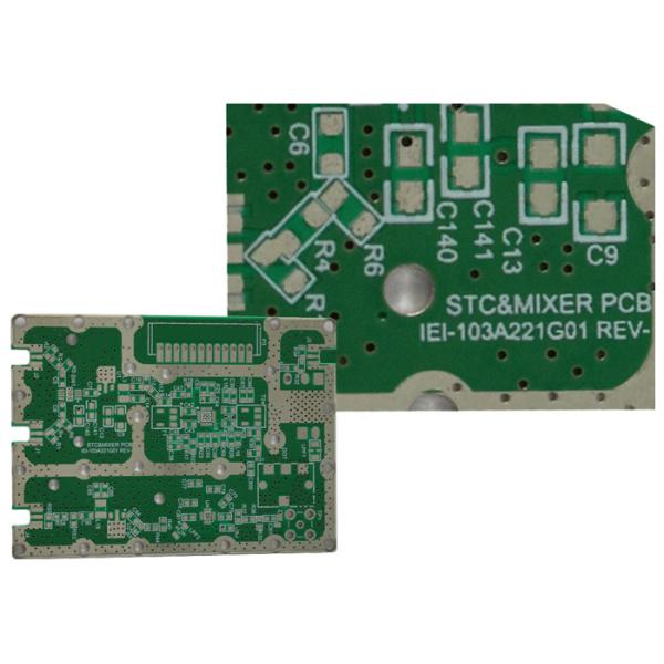
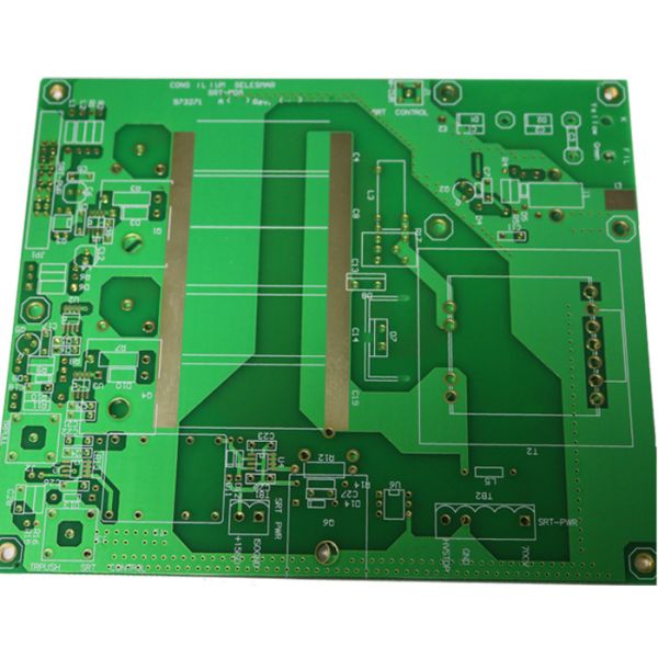
For many applications, it is sufficient to use Rogers material with an appropriate layer buildup. In addition, we process high-frequency materials with improved dielectric properties. These have a very low loss factor, a low dielectric constant, and are primarily temperature and frequency independent.
Additional favourable properties are high glass transition temperature, an excellent thermal durability, and very low hydrophilic rate.
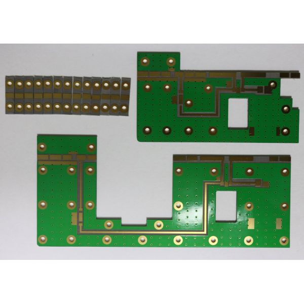
We use (among others) Rogers or PTFE materials (for example, Teflon from DuPont) for impedance controlled high frequency circuit boards. Sandwich buildups for material combinations are also possible.
Which widely be used for :
Automotive Antennas / RFID
Back-up Aids
Collision Avoidance
Low-Noise Block Downconverter (LNB)
Mobile Infrastructure Antennas
Point to Point Digital Radios
Power Amplifiers
High Reliability
Airborne Antenna Systems
Broadcast Satellites
Ground Based Radar Systems
Millimeter Wave Applications
Missile Guidance Systems
High Speed Digital
Rogers High frequency pcb material:
Model | Parameter | thickness(mm) | Permittivity(ER) |
F4B | F4B | 0.38 | 2.2 |
F4B | 0.55 | 2.23 | |
F4B | 0.225,0.3,0.5,08,1,1.2,1.5,2,2.5,3.0 | 2.65 | |
F4Bk | 0.8,1.5 | 2.65 | |
F4B | 0.8 | 3.5 | |
FE=F4BM | 1 | 2.2 | |
Rogers | RO5880 | 0.254 0.508 0.762 | 2.20 ± 0.02 |
RO4350 | 0.254 0.508,0.8,1.524 | 3.5 | |
RO4003 | 0.508 | 3.38 | |
TACONIC | TLF-35 | 0.8 | 3.5 |
TLA-6 | 0.254,0.8,1,1.5, | 2.65 | |
TLX-8 | 0.254,0.8,1,1.6 | 2.55 | |
RF-60A | 0.64 | 6.15 | |
TLY-5 | 0.254,0.508,0.8 | 2.2 | |
TLC-32 | 0.8,1.5,3 | 3.2 | |
TLA-35 | 0.8 | 3.2 | |
ARLON | AD255C06099C | 1.5 | 2.55 |
MCG0300CG | 0.8 | 3.7 | |
AD0300C | 0.8 | 3 | |
AD255C03099C | 0.8 | 2.55 | |
AD255C04099C | 1 | 2.55 | |
DLC220 | 1 | 2.2 |
Advantage
1. PCB factory directly
2. PCB Have the comprehensive quality control system
3. PCB good price
4. PCB quick turn delivery time from 48hours
5. PCB certification(ISO/UL E354810/RoHS)
6. 12 years experience in exporting service
7. PCB is no MOQ/MOV.
8. PCB is high quality.Strict through theAOI(Automated Optical Inspection),QA/QC,fly porbe ,Etesting
Some Typical Applications:
• Automotive radar applications
• Global positioning satellite
antennas
• Cellular telecommunications
systems - power amplifi ers and
antennas
• Patch antenna for wireless
communications
• Direct broadcast satellites
• Datalink on cable systems
• Remote meter readers
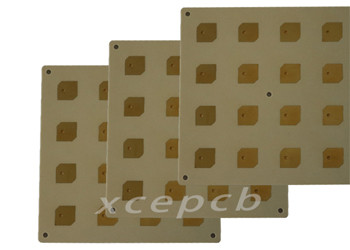
Rogers 4350B laminate in stock