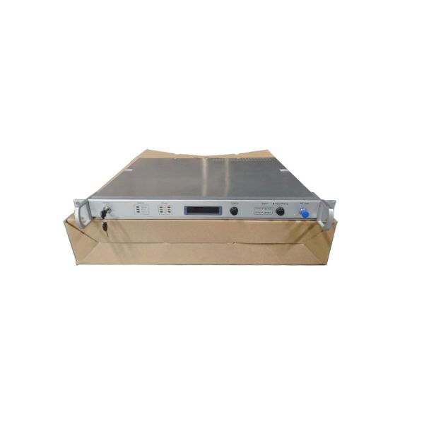
1310nm Fiber Optical RF Transmitter Optical Transmitter For CATV
JZOT1310
Overview:
Our company is a manufacturer specializing in the production of amplitude modulation optical transmitter, the receiver and the two-ways trunk line amplifier, and is well-known by it’ s formidable research and development ability and constant pursuit to remarkable quality. The products of the company have been following closely the latest development demand of the domestic and foreign CATV network continuously, trying hardly to provide the customers with HFC network equipment which meets the newest standards of the customers. The company not only sells the equipment both domestically and abroad. But also offers the other companies with equipment of OEM. The well-equipped functions of the optic-electric equipment, the high target in the course of the use and the redundant reliability have won the wide prestige for the company.
Main technical parameter:
Items | Unit | Technical Parameter | ||||||||
Output Optical Power | mW | 4-5 | 6-7 | 8-9 | 10-11 | 12-13 | 14-15 | 16-17 | 18-19 | 20-21 |
Optical Link Loss | dB | 7 | 9 | 10 | 11 | 12 | 13 | 14 | 15 | 16 |
Optical Output Wave Length | nm | 1310± 20 | ||||||||
Optical Connection Type | FC/APC or SC/APC | |||||||||
Frequency Range | MHz | 47-862 or 47-750 | ||||||||
Channels | way | 84 | ||||||||
Link C/N | dB | >51 | ||||||||
Link C/CTB | dB | >65 | ||||||||
Link C/CSO | dB | >61 | ||||||||
Output optical return loss | dB | >45 | ||||||||
Input level ① | dBμV | 75-85(①main input port inputs RF signal) | ||||||||
Input level ② | dBμV | 85-95(② auxiliary input interface inputs RF signal) 75-85(auxiliary input interface inputs numeral signal) | ||||||||
RF Flatness In Band | dB | ±0.5 | ||||||||
RF Input Return Loss | dB | >16 | ||||||||
Voltage | V | AC110-265(50Hz) | ||||||||
Power Loss | W | 24 | ||||||||
Operating Temperature | ℃ | 0-45 | ||||||||
Dimension | mm | 483× 355 ×44(19” × 14” ×1.75”) |
Front Panel Description
No. | Name | Function Descriptions |
1 | Laser key | Start the working circuit of the laser (off/on) |
2
| Display of LED on the Set | Optical: turn on the laser key, and the light is on when the optical signal output is normal. RF In: when RF input signal is connected, and>73dBuV, the light on. Alarm: When the failure give an alarm, the light on. |
3 | The Display of the Power | Display +24V, +5V and –5Vstatus of power module A, power module B accordingly. |
4 | LCD Screen | Display the parameter of the equipment and key working parameter |
5 | Display Button | Choose display contents of LCD |
6 | MGC adjusting button | Adjust MGC range , the maximum value is 8dB |
7 | AGC adjusting button | Adjust AGC range, the maximum value is 8dB |
8 | AGC status display | When the equipment is on AGC, the light on |
9 | MGC status display | When the equipment is on MGC, the light on |
10 | AGC/MGC Key | Choosing equipment is on AGC or MGC |
11 | RF monitoring interface | Monitor the drive level, when AGC or MGC is zero, that means main input level |
Warning Status | System Reflection |
RF input signal level is too high(>88dBμV) | Alarm light is on, the short voice of the buzzer gives an alarm, and cut off RF signal automatically.. |
Laser’s bias current is too high (>80mA) | Alarm light is on, the long voice of the buzzer gives an alarm, cut off laser power and RF signal. |
Laser’s cooling current is too high | Alarm light is on, the long voice of the buzzer gives an alarm, cut off laser power automatically. |
+5V power voltage deviates from the normal value(60%) | Alarm light is on, the long voice of the buzzer gives an alarm, cut off laser power automatically. |
-5V power voltage deviates from normal value(60%) | Alarm light is on, the long voice of the buzzer gives an alarm, cut off laser power automatically. |