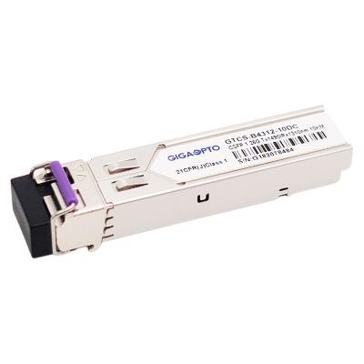
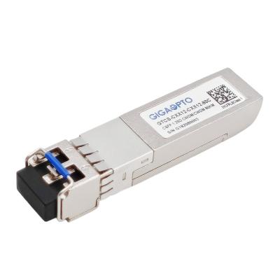
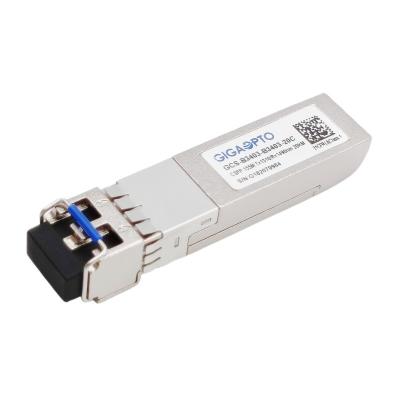
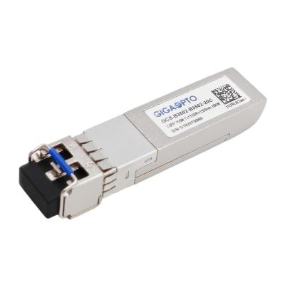
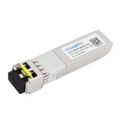
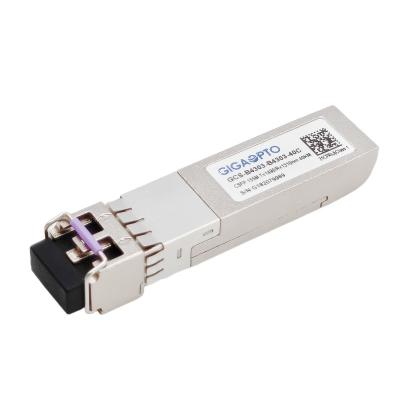
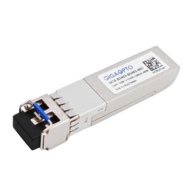
1.25G Compact SFP (CSFP) dual BIDI TX1310nm RX1490nm 20km LC DOM
Description
This 1000Base 2-fiber Bi-directional compact SFP Transceiver is a version of SFP with the same mechanical form factor allowing two independent bidirectional channels per port. It is designed to use in high density Gigabit Ethernet/1G Fiber Channel applications, providing 20km links using the nominal wavelength of TX1310nm/RX1490nm over standard single mode fiber.
It is with the SFP 20-pin connector to allow hot plug capability. Digital diagnostic functions are available via an I2C series bus specified in the MSA SFF-8472. The transmitter section uses a multiple quantum well 1310nm DFB laser and is a class 1 laser compliant according to International Safety Standard IEC 60825. The receiver section uses an integrated 1490nm detector preamplifier (IDP) mounted in an optical header and a limiting post-amplifier IC.
The CSFP transceiver is fully compliant to compact Small Form-Factor Pluggable (CSFP) MSA option 2 and SFF-8472.
Specifications
Product Series | Fiber CSFP Transceiver | Part Number | GCS-B3412-B3412-20C |
Form Factor | CSFP | Type | 2x BiDi LX |
Data Rate | 1.25G/1.25G | Lane Count | 2x (Tx/Rx) |
Distance | 20km | Connector | 2x LC-Simplex |
TX Wavelength | 2x 1310nm | RX Wavelength | 2x 1490nm |
Power Supply Voltage | +3.3V (typical) | Power Consumption | ≤ 1.3W |
Transmitter Type/Lane | FP | Receiver Type/Lane | PIN |
Transmitter Output Power | -9 ~ -3dBm | Receiver Sensitivity | < -22dBm |
Extinction Ratio | > 9dB | Input Overload | > -3dBm |
Power Budget (dB) | 13dB | Digital Diagnostic | Support |
Environment | Operating: 0 to 70°C | Warranty | 3-year |
Storage: -40°C to 85°C | Unit Weight | 25gram | |
Compliance | 1000Base BX20 IEEE802.3ah, CE, Class 1 FDA and IEC60825-1 Laser Safety Compliant, CSFP MSA option 2, IEEE 802.3z, RoHS, SFF-8472 |
Features
Application
Electrical and Optical Characteristics
Parameter | Symbol | Min | Typical | Max | Unit | Notes |
Power Consumption | 1.32 | W | ||||
Supply Current | Icc | 400 | mA | |||
Transmitter | ||||||
Single-ended Input Voltage Tolerance | -0.3 | 4.0 | V | |||
Differential Input Voltage Swing | Vin,pp | 200 | 2400 | mVpp | ||
Differential Input Impedance | Zin | 90 | 100 | 110 | Ohm | |
Transmit Disable Assert Time | 5 | us | ||||
Transmit Disable Voltage | Vdis | Vcc-1.3 | Vcc | V | ||
Transmit Enable Voltage | Ven | Vee-0.3 | 0.8 | V | ||
Receiver | ||||||
Differential Output Voltage Swing | Vout,pp | 500 | 900 | mVpp | ||
Differential Output Impedance | Zout | 90 | 100 | 110 | Ohm | |
Data output rise/fall time | Tr/Tf | 100 | ps | 20% to 80% | ||
LOS Assert Voltage | VlosH | Vcc-1.3 | Vcc | V | ||
LOS De-assert Voltage | VlosL | Vee-0.3 | 0.8 | V |
Parameter | Symbol | Min | Typical | Max | Unit | Notes |
Transmitter | ||||||
Center Wavelength | λC | 1260 | 1310 | 1360 | nm | |
Spectrum Bandwidth(RMS) | σ | 3.5 | nm | |||
Side Mode Suppression Ratio | SMSR | 30 | dB | |||
Average Optical Power | PAVG | -9 | -3 | dBm | 1 | |
Optical Extinction Ratio | ER | 9 | dB | |||
Transmitter OFF Output Power | POff | -45 | dBm | |||
Transmitter Eye Mask | Compliant with 802.3z(class 1 laser safety) | 2 | ||||
Receiver | ||||||
Center Wavelength | λC | 1470 | 1490 | 1510 | nm | |
Receiver Sensitivity (Average Power) | Sen. | -20 | dBm | 3 | ||
Input Saturation Power (overload) | Psat | -3 | dBm | |||
LOS Assert | LOSA | -36 | dB | 4 | ||
LOS De-assert | LOSD | -21 | dBm | 4 | ||
LOS Hysteresis | LOSH | 0.5 | 2 | 6 | dBm |
Notes:
1. Measure at 2^7-1 NRZ PRBS pattern
2. Transmitter eye mask definition.
3. Measured with Light source 1310nm, ER=9dB; BER =<10^-12 @PRBS=2^7-1 NRZ When LOS de-asserted, the RX data+/- output is High-level (fixed).
Pin Assignment and Pin Description
Diagram of host board connector block pin numbers and names
PIN | Name | Name/Description | Notes |
1 | VEE | Transmitter Ground | VEE may be internally connected within the SFP module |
2 | TX FAULT | Transmitter Fault. | TX Fault is an open collector/drain output, which should be pulled up with a 4.7K– 10K resistor on the host board. Note 1 for more information |
3 | TX1_Disable | Transmitter Disable of Ch A | Module channel A disables function |
4 | MOD_DEF2 | Two-wires interface Data | 2 wire serial ID interface, SDA |
5 | MOD_DEF1 | Two-wires interface Clock | 2 wire serial ID interface, SCL |
6 | TD2- | Inverted Transmit Data Input of Ch B | These are the differential transmitter puts. They are AC-coupled, differential lines with 100 differential termination inside the module. The AC coupling is done inside the module and is thus not required on the host board |
7 | TD2+ |
Transmit Data Input of Ch B | |
8 | LOS1 |
Loss of Signal of Ch A | Loss of Signal detected function. Note 2 for more information. |
9 | RD2+ | Received Data Output of Ch B | These are the differential receiver outputs. They are AC coupled 100 differential lines which should be terminated with 100(differential) at the user SERDES. The AC coupling is done inside the module and is thus not required on the host board. |
10 | RD2- |
Inverted Received Data Output of Ch B | |
11 | VEE |
Transceiver Ground | VEE may be internally connected within the SFP module. |
12 | RD1- | Inverted Received Data Output of Ch A | These are the differential receiver outputs. They are AC coupled 100 differential lines which should be terminated with 100(differential) at the user SERDES. The AC coupling is done inside the module and is thus not required on the host board. |
13 | RD1+ |
Received Data Output of Ch A | |
14 | LOS2 |
Loss of Signal of CH B | Loss of Signal detected function. Note 2 for more information. |
15 | VCCR | Receiver Power | 3.3V± 5%. Note 3 for more information |
16 | VCCT |
Transmitter Power | 3.3V± 5%. Note 3 for more information |
17 | TX2_Disable | Transmitter Disable of Ch B | Module channel B disables function |
18 | TD1+ |
Transmit Data Input of Ch A | These are the differential transmitter puts. They are AC-coupled differential lines with 100 differential termination inside the module. The AC coupling is done inside the module and is thus not required on the host board |
19 | TD1- | Inverted Transmit Data Input of Ch A | |
20 | VEE |
Transceiver Ground | VEE may be internally connected within the SFP module. |
Notes:
1. When high, output indicates a laser fault of some kind either in Channel A or Channel B. The Host shall read Channel A/B for details: TX Fault from channel A if bit 2 is set in [A2H:110]; TX Fault from channel B if bit 2 is set in [B2H: 110]. Low indicates normal operation. In the low state, the output will be pulled to < 0.8V.
2. When high, this output indicates the received optical power is below the worst-case receiver sensitivity (as defined by the standard in use). Low indicates normal operation. In the low state, the output will be pulled to < 0.4V. VccT VccR are the power supplies. They are defined as 3.3V ±5% at the SFP connector pin. Maximum supply current is 400Ma@3.3V. Vcc may be internally connected within the SFP transceiver module.
Mechanical Dimensions
Dimensions are in millimeters. All dimensions are ±0.1mm unless otherwise specified. (Unit: mm)