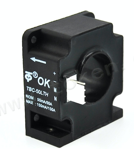
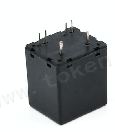
Ac Dc Current Sensor Closed Loop Hall Effect Current Sensor CE ROHS
The TBC-LTH/LTR Series current sensor is a closed loop device based on the measuring principle of the hall effect and null balance method , with a galvanic isolation between primary and secondary circuit, the size of primary doesn’t affect test precision, no matter the location of primary in the hole of current sensor, It can really measure resolution 1000:1 and uses for precision measurement of DC, AC and pulse current.
Electrical data(Ta=25℃±5℃) |
Type
| TBC50 LTH/LTR | TBC100 LTH/LTR | TBC150 LTH/LTR | TBC200 LTH/LTR | TBC300 LTH/LTR | TBC300 LTH/LTR | Unit |
Rated current(Ipn) | 5-50 | 10-100 | 30-150 | 20-200 | 30-300 | 30-300 | A |
Measure range(Ip) | 150(±18V,82Ω) | 300(±18V,30Ω) | 450(±18V,33Ω) | 450(±18V,33Ω) | 900(±18V,3.0Ω) | 900(±18V,2.0Ω) | A |
Turns ratio(Np/Ns) | 1:1000 | 1:1000 | 1:1500 | 1:2000 | 1:2000 | 1:3000 | |
with ±12V | @50Amax 180(max) | @100Amax 75(max) | @150Amax 90(max) | @200Amax 90(max) | @300Amax 48(max) | @300Amax 68(max) | Ω |
@150Amax 40(max) | @300Amax 12(max) | @300Amax 33(max) | @600Amax 15(max) | @600Amax 10(max) | @600Amax 1.0(max) | Ω | |
with ±15V | @50Amax 240(max) | @100Amax 110(max) | @150Amax 120(max) | @200Amax 120(max) | @300Amax 70(max) | @300Amax 91(max) | Ω |
@150Amax 60(max) | @300Amax 20(max) | @300Amax 50(max) | @600Amax 25(max) | @600Amax 20(max) | @750Amax 2.0(max) | Ω | |
Rated output (Isn) | 5(5A)- 50(50A) ±0.2% | 10(10A)- 100(100A) ±0.2% | 20(30A)- 100(150A) ±0.2% | 10(20A)- 100(200A) ±0.2% | 15(30A)- 150(300A) ±0.2% | 10(30A)- 100(300A) ±0.2% | mA |
Coil resister | 30 | 25 | 20 | 30 | 28 | 53 | Ω |
Supply voltage | ±12~±18 | V | |||||
Power consumption | ≤20+IpXNs | mA | |||||
Offset current | @Ip=0 ≤±0.2 | mA | |||||
Offset drift | @ -40℃~85℃ ±0.5 | mA | |||||
Response time | @100A/μS,10%-90% <1.0 | µs | |||||
Linearity | @Ip=0-±Ipn ≤0.1 | %FS | |||||
Galvanic isolation | @ 50HZ,AC,1min 3 | KV | |||||
di/dt | >100 | A/µs | |||||
Bandwidth | @ -3db DC…100 | KHz |
Applications |
Variable speed drives
Welding machine
Battery supplied applications
Uninterruptible Power Supplies (UPS)
Electrochemical
Mechanical dimension(for reference only) |
Remarks:
1. All dimensions are in mm.
2. General tolerance ±1mm
Directions for use |
Is will be in a forward direction when the Ip flows according to the direction of the arrowhead.
The primary conductor should be≤120℃.
The dynamic performance (di/dt and the response time) is the best when the primary hole is fully filled with the bus bar.
Standards |
General date |
Value | Unit | Symbol | |
Operating temperature | -40 to +85 | ºC | TA |
Storage temperature | -40 to +125 | ºC | TS |
Mass(approx) | LTH:58,LTR:64 | g | M |
Characteristics chart |
Pulse current signal response characteristic Effects of impulse noise