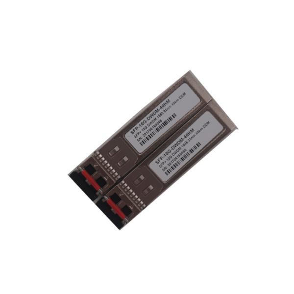
10G LR SFP+ Transceiver made in China
Features
● Duplex LC Connector
● Support hot-pluggable
● Metal with lower EMI
● Excellent ESD protection
● DFB Transmitter and PIN Receiver
● Typical Center Wavelength:1310nm
● Max link length up to 10Km on SMF
● RoHS Compliant and Lead-Free
● Digital diagnostic compatible with SFF-8472
● Case Operation Temperature:-5℃~+70℃
● Single 3.3V power supply and Low power dissipation <1.0W
Description
HD-SFP+/10G-LR is specifically designed for the high performance integrated duplex data transmission over single mode optical fiber. This transceiver module is compliant with the Small Form-factor Pluggable Plus (SFP+) Multisource Agreement (SFF-8431 Rev4.1).This transceiver type is specifically optimized for transport of serial data at up to 10.3125 Gbps, with link characteristics complied with 10-Gigabit Ethernet 10GBASE-LR base IEEE 802.3ae and 10G Fibre Channel 1200-SM-LL-L. 5
Applications
● 10GBASE-LR/LW 10G Ethernet
● 1200-SM-LL-L 10G Fibre Channel
aximum Ratings
Parameter | Symbol | Min. | Typ. | Max. | Unit | Notes |
Maximum Supply Voltage | Vcc3 | -0.5 | - | 4.0 | V | |
Storage Temperature | TS | -40 | - | 85 | °C | |
Operating Humidity | - | 5 | - | 95 | % | |
Maximum Supply Voltage | Vcc3 | -0.5 | - | 4.0 | V |
Recommended Operating Conditions |
Parameter | Symbol | Min. | Typ. | Max. | Unit | Notes |
Power Supply Voltage | Vcc | 3.13 | 3.30 | 3.47 | V | |
Power Supply Current | Icc | - | - | 300 | mA | |
Case Operating Temperature | Top | -5 | - | 70 | °C | |
Data Rate | - | - | 10.3125 | - | Gb/s | |
9/125um G652 SMF | Lmax | - | - | 10 | Km | |
Baud Rate Tolerance | -100 | +100 | ppm |
Performance Specifications - Transmitter |
(-5ºC<Tc<+70°C; +2.97V<Vcc<+3.63V)
Parameter | Symbol | Min. | Typ. | Max. | Unit | Notes | |
Input Differential Impedance | Zin | 90 | 100 | 110 | Ω | ||
Tx_Fault | Normal Operation | VOL | -0.3 | - | 0.4 | V | |
Transmitter Fault | VOH | 2.4 | - | Vcc | V | ||
TX_Disable (Note 1) | Disable | VIH | 2.0 | - | Vcc+0.3 | V | |
Enable | VIL | -0.3 | - | 0.8 | V | ||
Average Launch Optical Power | Pout | -8.2 | - | 0.5 | dBm | ||
Optical modulation amplitude | P(OMA) | -5.2 | -2 | dBm | |||
Extinction Ratio | ER | 3.5 | 5 | - | dB | ||
Transmitter and Dispersion Penalty | TDP | - | - | 3.2 | dB | ||
Average Launch power of OFF TX | Poff | - | - | -30 | dBm | ||
Optical Wavelength | λ | 1260 | 1355 | nm | |||
Side mode Suppression Ratio | SMSR | 30 | dB | ||||
Relative Intensity Noise(OMA) | RIN12 | -130 | dB/Hz | ||||
Optical Return Loss Tolerance | ORLT | 12 | dB | ||||
Eye Diagram | Compatible with IEEE 802.3-2005 |
Performance Specifications - Receiver |
(-5C<Tc<+70°C; +2.97V<Vcc<+3.6V)
Parameter | Symbol | Min. | Typ. | Max. | Unit | Notes |
Differential Data Output Swing | Vout | 300 | - | 800 | mV | |
Output Differential Impedance | Zin | 90 | 100 | 110 | Ω | |
Receiver sensitivity (max) in OMA | PIN-SENS(OMA) | - | - | -12.6 | dBm | BER<10E-12; PRBS2^31 |
Receiver Sensitivity | PIN-SENS | - | - | -14.4 | dBm | |
Overload | 0.5 | - | - | dBm | ||
Receiver reflectance | - | - | - | -12 | dB | |
Optical Center Wavelength | λC | 1270 | - | 1600 | nm | |
Los Assert | -32 | - | - | dBm | ||
Los De-assert | - | - | -18 | dBm | ||
Los hysteresis | 0.5 | - | - | dB |
Pin Function Definitions
|
Pin Num | Name | Function | Plug Seq. | Notes |
1 | VeeT | Module Transmitter Ground | 1 | |
2 | Tx_FAULT | Module Transmitter Fault | 3 | Note 1 |
3 | Tx_DISABLE | Transmitter Disable; Turns off transmitter laser output | 3 | Note 2, Module disables on high or open |
4 | SDA | 2-wire Serial Interface Data Line (Same as MOD-DEF2 in INF-8074i) | 3 | |
5 | SCL | 2-wire Serial Interface Clock (Same as MOD-DEF1 in INF-8074i) | 3 | |
6 | MOD-ABS | Module Absent, connected to VeeT or VeeR in the module | 3 | |
7 | RS0 | Rate Select 0, optionally controls SFP+ module receiver. | 3 | Note 3 |
8 | Rx_LOS | Receiver Loss of Signal Indication (In FC designated as Rx_LOS, in SONET designated as LOS and in Ethernet designated as Signal Detect) | 3 | Note 4 |
9 | RS1 | Rate Select 1, optionally controls SFP+ module transmitter | 1 | Note 3 |
10 | VeeR | Module Receiver Ground | 1 | Note 5 |
11 | VeeR | Module Receiver Ground | 1 | Note 5 |
12 | RD- | Receiver Inverted Data Output | 3 | Note 6 |
13 | RD+ | Receiver Non-Inverted Data Output | 3 | Note 6 |
14 | VeeR | Module Receiver Ground | 1 | Note 5 |
15 | VccR | Module Receiver 3.3 V Supply | 2 | 3.3 ± 10%, Note 7 |
16 | VccT | Module Transmitter 3.3 V Supply | 2 | 3.3 ± 10%, Note 7 |
17 | VeeT | Module Transmitter Ground | 1 | Note 5 |
18 | TD+ | Transmitter Non-Inverted Data Input | 3 | Note 8 |
19 | TD- | Transmitter Inverted Data Input | 3 | Note 8 |
20 | VeeT | Module Transmitter Ground | 1 | Note 5 |
Notes:
Low (0 – 0.8V): Transmitter on
(>0.8, < 2.0V): Undefined
High (2.0 – 3.465V): Transmitter Disabled
Open: Transmitter Disabled
These contacts can also be used for AS0 and AS1 if implementing SFF8079. See SFF8079 for details. RS1 is commonly connected to VeeT or VeeR in the classic SFP modules. The host needs to ensure that it will not be damaged if this contact is connected to VeeT or VeeR in the module.
The SFP+ module provides two inputs RS0 and RS1 that can optionally be used for rate selection. RS0 controls the receive path signalling rate capability, and RS1 controls the transmit path signalling rate capability. The host and module may choose to use either, both, or none of these functions. Because contact 9 in the classic SFP INF-8074i is connected to VeeR, an SFP+ host utilizing RS1 must provide short circuit protection.
This rate select functionality can also be controlled by software as defined by SFF-8472. Optionally the rate select methods of Part 2 of SFF-8079 may be used instead of the method described here by setting the management declaration bit (A0h byte 93 bit 2) to 1, see SFF-8472.
Rx_LOS when high indicates an optical signal level below that specified in the relevant standard. Rx_LOS is an open drain/collector output, but may also be used as an input by supervisory circuitry in the module. For a nominally 3.3 V Vcc_Host using a resistive pull up to Vcc_Host the resistor value shall be in the range 4.7 kΩ to 10 kΩ. For a nominally 2.5 V Vcc_Host using a resistive pull up to Vcc_Host the resistor value shall be in the range 4.7 kΩ to 7.2 kΩ.
The Rx_LOS signal is intended as a preliminary indication to the host in which the module is installed that the received signal strength is below the specified range. Such an indication typically points to non-installed cables, broken ca-bles, or a disabled, failing or a powered off transmitter at the far end of the cable. Additional indications are provided by the host in which the module is installed to verify that the information being transmitted is valid, correctly en-coded, and in the correct format. Such additional indications are outside the scope of the module specification.
Rx_LOS may be an optional function depending on the supported standard. If the Rx_LOS function is not implemented, or is reported via the two-wire inter-face only, the Rx_LOS contact shall be held low by the module and may be con-nected to Vee within the module.
Rx_LOS assert min and de-assert max are defined in the relevant standard. To avoid spurious transition of Rx_LOS a minimum hysteresis of 0.5 dBo is recom-mended.
Regulatory Compliance |
● Compliant with SFP+ MSA: SFF-8431 Rev4.1
● Compliant with SFF-8472 Rev4.4
● Compliant with IEEE802.3ae
● ESD to the Electrical PINs: compatible with MIL-STD-883E Method 3015.7
● ESD to the Duplex LC Receptacle: compatible with IEC 61000-4-2 GR-1089-CORE
● Immunity compatible with IEC 61000-4-3
● EMI compatible with FCC Part 15 Class B EN55022 Class B (CISPR 22B) VCCI Class B
● Laser Eye Safety compatible with FDA 21CFR 1040.10 and 1040.11 EN60950, EN (IEC) 60825-1,2
● RoHS compliant with 2002/95/EC 4.1&4.2 2005/747/EC
10G LR SFP+ Transceiver made in China