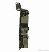
Electronic Lock HDI Pcb Board Doorbell PCB & Pcba Assembly Camera Copper SMT Assembly
- Use little soldermask: most soldermasks have a high moisture absorption capacity. In case this happens, high losses can occur in the circuit;
- Use perfectly smooth copper traces and plans: The current skin depth, in fact, is inversely proportional to the frequency and therefore, on a printed circuit board with high frequency signals, it is very shallow. An irregular copper surface will offer the current an irregular path, increasing the resistive losses;
- Signal integrity: High frequencies represent one of the most difficult challenges for the integrated circuit designer. In order to maximize I/O, high density interconnections (HDI) require thinner tracks, a factor that can cause signal degradation leading to further losses. These losses adversely affect the transmission of the RF signal, which can be delayed for several milliseconds, in turn causing problems in the signal transmission chain. In high frequency domain, signal integrity is almost entirely based on checking impedance. Traditional PCB manufacturing processes, such as the subtractive process, have the disadvantage of creating tracks with a trapezoidal cross section (the angle, compared to the vertical perpendicular to the track, is normally between 25 and 45 degrees). These cross sections modify the impedance of the tracks themselves, placing serious limits on 5G applications. However, the problem can be solved by using the mSAP (Semi-Additive fabrication Process) technique, which allows to create traces with greater precision, allowing trace geometries to be defined via photolithography. In Figure 2 we can see a comparison of the two manufacturing processes.
1. Product application
Any layer of interconnect board products can be applied to mobile communication terminals, which integrates a variety of circuits, enabling mobile terminals to handle complex tasks and have rich communication methods. With the development of communication technologies, mobile terminals have become modern Internet services. The main platform.
2 . Specifications:
Name |
10Layer anylayer HDI PCB for 5G mobile phone motherboard |
Layer |
10 |
Quality Grade |
IPC 6012 Class 2,IPC 6012 Class 3 |
Material |
EM370 |
Min Track/Spacing |
75um/100um |
Drilling Size |
100um |
Solder Mask |
Green |
Silkscreen |
White |
Surface Finish |
Immersion gold |
Finished Copper |
1/3OZ |
Production time |
10-21 working days |
Lead time |
2-3 days
|
PCBs for high frequency applications require to be subjected to automatic inspection procedures, both optical (AOI) or performed through ATE. These procedures allow to enormously increase the quality of the product, highlighting possible errors or inefficiencies of the circuit. The recent progress made in the field of automatic inspection and testing of PCBs has led to significant time savings and reduced costs associated with manual verification and testing. The use of new automated inspection techniques will help overcome the challenges imposed by 5G, including global impedance control in high frequency systems. Increased adoption of automated inspection methods also allows for consistent performance with high production rates.